
If you’ve already created an alignment and profile view—for example, if you’re going to show your pipes on the same profile view as your road design—select a network part, right-click, and choose Draw Parts In Profile from the Network Tools panel. When you’re using this command, it’s important to note that only selected parts are drawn in your chosen profile view.
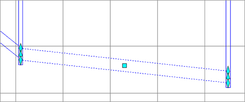
If you neglect to choose specific parts that are meaningful to show in your profile view, you’ll end up with a result like the one shown in Figure 13-52.
Figure 13-52: A profile view with inappropriate pipe network parts drawn on it

Also keep in mind when adding parts to your profile view that depending on the location of your alignment with respect to your pipes and structures, the labeled length from the model may not be the same as a pipe length you scale or measure from the profile view.
Profiles and profile views are always cut with respect to an alignment. Therefore, pipes are shown in the profile view on the basis of how they appear along that alignment or how they cross that alignment. Unless your alignment exactly follows the centerline of your network parts, your pipes will likely show some drafting distortion.
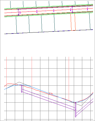
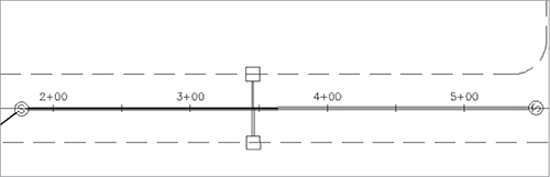
Let’s look at Figure 13-53 as an example. This particular jurisdiction requires that all utilities be profiled along the road centerline. There’s a road centerline, a Storm network that jogs across the road to connect with another catch basin.
Figure 13-53: These pipe lengths will be distorted in profile view.

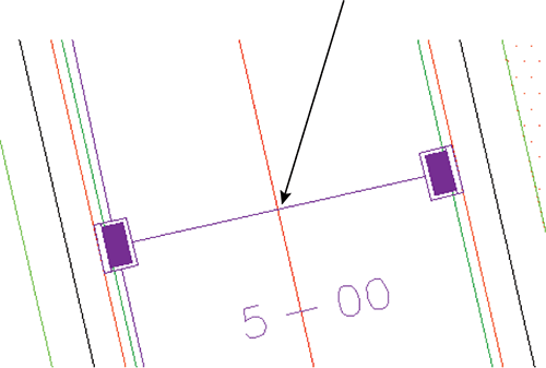
At least two potentially confusing elements show up in your profile view. First, the distance between structures (2D Length – Center To Center) isn’t the same in plan and profile (see Figure 13-54) because the storm pipe doesn’t run parallel to the alignment. Because the labeling reflects the network model, all labeling is true to the 2D Length – Center To Center or any other length you specify in your label style.
Figure 13-54: Pipe labels in plan view (top) and profile view (bottom)
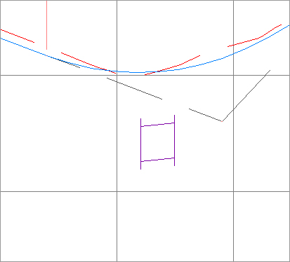
The second potential issue is that the invert of your crossing storm pipe is shown at the point where the storm pipe crosses the alignment and not at the point where it crosses the sanitary pipe (see Figure 13-55).
Figure 13-55: The invert of a crossing pipe is drawn at the location where it crosses the alignment.
Vertical Movement Edits Using Grips in Profile
Although you can’t make changes to certain part properties (such as pipe length) in profile view, pipes and structures both have special grips for changing their vertical properties in profile view.
When selected, a structure has two grips in profile view (see Figure 13-56). The first is a triangular-shaped grip representing a rim insertion point. This grip can be dragged up or down and affects the model structure-insertion point.
Figure 13-56: A structure has two grips in profile view.
Moving this grip can affect your structure insertion point two ways, depending on how your structure properties were established:
- If your structure has Automatic Surface Adjustment set to True, grip-editing this Rim Insertion Point grip changes the surface adjustment value. If your reference surface changes, then your rim will change along with it, plus or minus that surface adjustment value.
- If your structure has the Automatic Surface Adjustment set to False, grip-editing this Rim grip modifies the insertion point of the rim. No matter what happens to your reference surface, the rim will stay locked in place.
Typically, you’ll use the Rim Insertion Point grip only in cases where you don’t have a surface for your rims to target to or if you know there is a desired surface adjustment value. It’s tempting to make a quick change instead of making the improvements to your surface that are fundamentally necessary to get the desired rim elevation. One quick change often grows in scope. Making the necessary design changes to your target surface will keep your model dynamic and, in the long run, will make editing your rim elevations easier.
The second grip is a triangular grip located at the sump depth. This grip doesn’t represent structure invert. In Civil 3D, only pipes truly have invert elevation. The structure uses the connected pipe information to determine how deep it should be. When the sump has been set at a depth of 0, the sump elevation equals the invert of the deepest connected pipe.
This grip can be dragged up or down. It affects the modeled sump depth in one of two ways, depending on how your structure properties are established:
- If your structure is set to control sump by depth, editing with the Sump grip changes the sump depth. The depth is measured from the structure insertion point. For example, if the original sump depth was 0, grip-editing the sump 0.5′ (15.24 cm) lower would be the equivalent of creating a new sump rule for a 0.5′ (15.24 cm) depth and applying the rule to this structure. This sump will react to hold the established depth if your reference surface changes, your connected pipe inverts change, or something else is modified that would affect the invert of the lowest connected pipe. This triangular grip is most useful in cases where most of your pipe network will follow the sump rule applied in your parts lists, but selected structures need special treatment.
- If your structure is set to control sump by elevation, adjusting the Sump grip changes that elevation. When sump is controlled by elevation, sump is treated as an absolute value that will hold regardless of the structure insertion point. For example, if you grip-edit your structure so its depth is 8.219′ (2.51 m), the structure will remain at that depth regardless of what happens to the inverts of your connected pipes. The Control Sump By Elevation parameter is best used for existing structures that have surveyed information of absolute sump elevations that won’t change with the addition of new connected pipes.
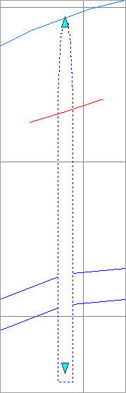
When selected, a pipe end has three grips in profile view (see Figure 13-57). You can grip-edit the invert, crown, and centerline elevations at the structure connection using these grips, resulting in the pipe slope changing to accommodate the new endpoint elevation.
Figure 13-57: Three grips for a pipe end in profile view
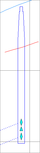
When selected, a pipe in profile view has one grip at its midpoint (see Figure 13-58). You can use this grip to move the pipe vertically while holding the slope of the pipe constant.
Figure 13-58: Use the Midpoint grip to move a pipe vertically.
You can access pipe or structure properties by choosing a part, right-clicking, and choosing Pipe Properties.
Removing a Part from Profile View
If you have a part in profile view that you’d like to remove from the view but not delete from the pipe network entirely, you have a few options.
AutoCAD Erase can remove a part from profile view; however, that part is then removed from every profile view in which it appears. If you have only one profile view, or if you’re trying to delete the pipe from every profile view, this is a good method to use.
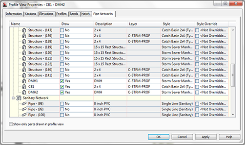
A better way to remove parts from a particular profile view is through the profile view properties. You can access these properties by selecting the profile view, right-clicking, and choosing Profile View Properties.
The Pipe Networks tab of the Profile View Properties dialog (see Figure 13-59) provides a list of all pipes and structures that are shown in that profile view. You can deselect the check boxes next to parts you’d like to omit from this view. Also note that you can add parts to your view by deselecting the Show Only Parts Drawn In Profile View check box and making changes in the Draw column.
Figure 13-59: Deselect parts to omit them from a view.
Showing Pipes That Cross the Profile View
If you have pipes that cross the parent alignment of your profile view, you can show them with a crossing style. A pipe must cross the parent alignment to be shown as a crossing in profile, and the vertical location of the pipe is shown where it crosses that alignment (see Figure 13-60).
Figure 13-60: A pipe crossing a profile

For example, if you created an alignment directly from your network parts and then created a profile view for that alignment, any crossing pipes would be shown at the elevation where they cross the main run because your alignment and pipes coincide (see Figure 13-61).
Figure 13-61: The invert of a storm crossing that runs along an alignment is shown in profile at the elevation where it crosses the sanitary line.
If a leg of a pipe network runs offset from the road centerline, such as that shown in Figure 13-62, but you’re showing those pipes in profile along the centerline alignment, any crossing pipes are shown where they intersect the road centerline alignment.
Figure 13-62: The invert of a storm crossing that is offset from the alignment is shown in profile at the elevation where it crosses the alignment.

When pipes enter directly into profiled structures, they can be shown as ellipses through the Display tab of the Structure Style dialog (see Figure 13-63). See Chapter 19, “Styles,” for more information about creating structure styles.
Figure 13-63: Pipes that cross directly into a structure can be shown as part of the structure style.

The first step to display a pipe crossing in profile is to add the pipe that crosses your alignment to your profile view by either selecting the pipe, right-clicking, and selecting Draw Parts In Profile from the Network Tools panel, or by checking the appropriate boxes on the Pipe Network tab of the Profile View Properties dialog. When the pipe is added, it’s distorted when it’s projected onto your profile view—in other words, it’s shown as if you wanted to see the entire length of pipe in profile (see Figure 13-64).
Figure 13-64: The pipe crossing is distorted.
The next step is to override the pipe style in this profile view only. Changing the pipe style through pipe properties won’t give you the desired result. You must override the style on the Pipe Networks tab of the Profile View Properties dialog (see Figure 13-65).
Figure 13-65: Correct the representation in the Profile View Properties dialog.
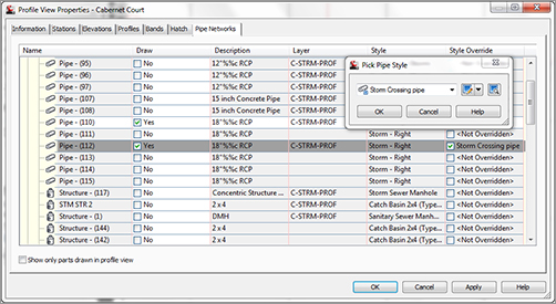
Locate the pipe you just added to your profile view, and scroll to the last column on the right (Style Override). Select the Style Override check box, and choose your pipe crossing style. Click OK. Your pipe should now appear as an ellipse.
If your pipe appears as an ellipse but suddenly seems to have disappeared in the plan and other profiles, chances are good that you didn’t use the Style Override but accidentally changed the pipe style. Go back to the Profile View Properties dialog, and make the necessary adjustments; your pipes will appear as you expect.
Exploring the Tools on the Pipe Network Tab
We have already looked at some of the tools available on the Pipe Networks tabs. You can access this tab by clicking on any pipe or structure. In this section, we will look at these tools.
The Labels & Tables Panel
The Labels & Tables Panel is where you do the most annotation labeling for pipes. It can either be selected from the Panel, or if you click on a pipe network, you can choose from the contextual menu.
Add Labels You can add labels for the selected pipe network using the suboptions such as Entire Network Plan, Entire Network Profile, Entire Network Section, Single Part Plan, Single Part Profile, Single Part Section, Spanning Pipes Plan, and Spanning Pipes Profile.
Add Tables You can add a structure or pipe table.
Reset Labels This will allow you to reset a label that is referenced in the drawing to match the labels that are set within the drawing.
The General Tools Panel
While not specifically for pipe networks or even Civil 3D for that matter, these tools are placed here for convenience.
Properties Toggles the Properties palette on and off.
Object Viewer Allows you to view the selected object or objects in 3D via a separate viewer.
Isolate Objects Selected objects will be the only objects visible on the screen. This is useful if you are working in a tight area and do not wish to see extraneous objects, and it is much quicker than clicking to turn off or freeze layers.
These tools are available via the General Tools panel drop-down:
Select Similar When this tool is invoked, it will select all similar type objects.
Quick Select or QSelect Opens the Quick Select dialog, which allows custom filtering.

Draw Order Icons Allow you to move objects either to the front or back of other objects, or above or behind a specific object.
Google Earth Timespan Opens the Timespan For Google Earth dialog, where you can set specific times for use in Google Earth. This will allow you to view your model in Google Earth with the specified times. It is useful for sun/shade studies.
The Modify Panel
The Modify Panel is where you do editing of an existing pipe network. It can also be selected by clicking on a pipe network and selecting it from the contextual menu.
Network Properties tool Opens the Pipe Network Properties dialog.
Pipe Properties Tool Opens the Pipe Properties dialog. This tool only works when a pipe is the selected object.
Edit Pipe Style Tool Opens the Pipe Style dialog. This tool only works when a pipe is the selected object. For more on pipe styles, see Chapter 19.
Structure Properties Tool Opens the Structure Properties dialog. This tool only works when a structure is the selected object.
Edit Structure Style Tool Opens the Structure Style dialog. This tool only works when a structure is the selected object. For more on structure styles, see Chapter 19.
Edit Pipe Network Tool Opens the Network Layout Tools toolbar.
Connect and Disconnect Part Tools Allow you to connect pipes to structures that may have been disconnected and to disconnect pipes from structures.
Swap Part Tool Allows you to replace a structure or pipe type with another one from a Swap Part Size dialog.
Split and Merge Network Tools Allow you to take an existing network and split it into two networks, or take an existing pipe network and merge it onto another pipe network.
The Modify panel drop-down list contains the following tools:
Rename Parts Tool Opens the Rename Pipe Network Parts dialog. Here, you can rename pipes and structures, modify pipe numbering, and decide how you want to handle conflicting names or numbers.
Apply Rules Tool Forces the set rule on the selected objects.
Change Flow Direction Tool Changes the path of the selected objects. It is very important to have this option set correctly if you are going to use any of the analysis programs.
The Network Tools Panel
The Network Tools panel contains the following tools:
Create Parts List Allows you to create new parts list via the Network Parts List – New Parts List dialog.
Create Full Parts List Takes all the parts available in the parts catalog and creates a list called Full Catalog.
Edit Parts List Opens the Parts List dialog, where you can select the network to add to an existing or new pipe network.
Set Network Catalog Opens the Pipe Network Settings dialog, where you can select whether you wish to use Imperial or Metric parts, and also sets the location of the Network Catalog.
Part Builder Opens the Part Builder tool.
Draw Parts In Profile View Adds the selected pipe network objects into an existing profile.
The Analyze Panel
The Analyze Panel contains the following tools for doing various checks on a pipe network.
Interference Check Properties Allows you to create an interference check between parts, whether or not they are on the same network. The following tools are available via the submenu:
Create Interference Check Tool This is the same as the Interference Check Properties tool.
When you select the Interference Check Properties tool, you are prompted to select Interference and then the Interference Check Properties dialog opens. The Information tab displays basic information such as the name of the interference set, style, rendering material, and layer. The Criteria tab contains specific editable items, such as whether to use 3D proximity check, distance, and scale factors. The Statistics tab is a combined listing of the other tabs but also allows you to see the networks used for the interference check.
Interference Properties Tool This may seem similar to the Interference Check Properties tool, even down to the Interference Check Properties dialog. It contains an Information tab (where you can name the individual interference objects) and a Statistics tab (which contains the X-Y location of the selected interference object).
Edit Interference Style Tool Opens the Interference Style dialog, where you can change the visual parameters for the interference object. For more on interference styles, see Chapter 19.
Storm Sewers Tool Gives you options for importing, exporting, and editing within the Storm Sewers program.
Edit In Storm And Sanitary Analysis Tool Opens the Storm and Sanitary Analysis (SSA) program. For more on SSA, see Chapter 14, “Storm and Sewer Analysis.”
The Launch Pad Panel
The Launch Pad Panel contains the following tools:
Alignment From Network Allows you to create an alignment from Pipe Network parts.
Storm Sewers Tool Opens the Hydroflow Storm Sewers program.
Hydrographs Tool Opens the Hydraflow Hydrographs program.
Express Tool Opens the Hydraflow Express program.