
Creating a Sanitary Sewer Network
Earlier, you prepared a parts list for a typical sanitary sewer network. This chapter will lead you through several methods for using that parts list to design, edit, and annotate a pipe network.
There are several ways to create pipe networks. You can do so using the Civil 3D pipe layout tools. Limited tools are also available for creating pipe networks from certain AutoCAD and Civil 3D objects, such as lines, polylines, alignments, and feature lines.
Creating a Pipe Network with Layout Tools
Creating a pipe network with layout tools is much like creating other Civil 3D objects, such as alignments. After naming and establishing the parameters for your pipe network, you’re presented with a special toolbar that you can use to lay out pipes and structures in plan, which will also drive a vertical design.
Establishing Pipe Network Parameters
This section will give you an overview of establishing pipe network parameters. Use this section as a reference for the exercises in this chapter. When you’re ready to create a pipe network, select Pipe Network Pipe Network Creation Tools from the Create Design panel on the Home tab. The Create Pipe Network dialog appears (see Figure 13-26), and you can establish your settings.
Figure 13-26: The Create Pipe Network dialog

Before you can create a pipe network, you must give your network a name, but more important, you need to assign a parts list for your network. As you saw earlier, the parts list provides a toolkit of pipes, structures, rules, and styles to automate the pipe network design process. It’s also important to select a reference surface in this interface. This surface will be used for rim elevations and rule application.
When creating a pipe network, you’re prompted for the following options:
Network Name Choose a name for your network that is meaningful and that will help you identify it in Prospector and other locations.
Network Description The description of your pipe network is optional. You might make a note of the date, the type of network, and any special characteristics.
Network Parts List Choose the parts list that contains the parts, rules, and styles you want to use for this design.
Surface Name Choose the surface that will provide a basis for applying cover rules as well as provide an insertion elevation for your structures (in other words, rim elevations). You can change this surface later or for individual structures. For proposed pipe networks, this surface is usually a finished ground surface.
Alignment Name Choose an alignment that will provide station and offset information for your structures in Prospector as well as any labels that call for alignment stations and/or offset information. Because most pipe networks have several branches, it may not be meaningful for every structure in your network to reference the same alignment. Therefore, you may find it better to leave your Alignment option set to None in this dialog and set it for individual structures later using the layout tools or structure list in Prospector.
Using the Network Layout Creation Tools
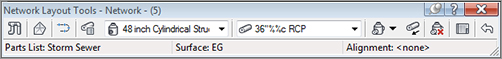
After establishing your pipe network parameters in the Create Pipe Network dialog (shown previously in Figure 13-26), click OK; the Network Layout Tools toolbar appears (see Figure 13-27). No other command can be executed while the toolbar is active.
Figure 13-27: The Network Layout Tools toolbar
Clicking the Pipe Network Properties tool displays the Pipe Network Properties dialog, which contains the settings for the entire network. If you mistyped any of the parameters in the original Create Pipe Network dialog, you can change them here. In addition, you can set the default label styles for the pipes and structures in this pipe network.
The Pipe Network Properties dialog contains the following tabs:
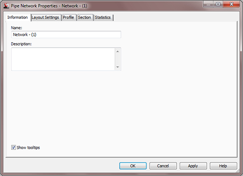
Information On this tab, you can rename your network, provide a description, and choose whether you’d like to see network-specific tooltips (see Figure 13-28).
Figure 13-28: The Information tab of the Pipe Network Properties dialog
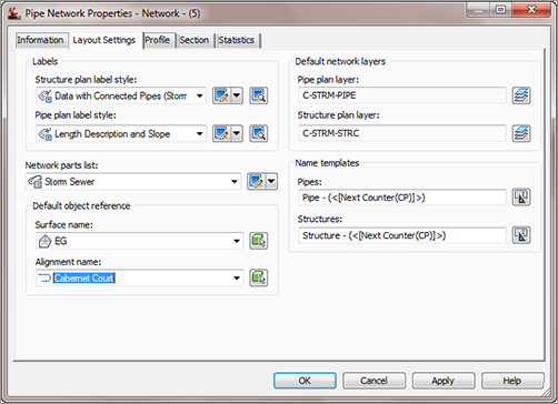
Layout Settings Here you can change the default label styles, parts list, reference surface and alignment, master object layers for plan pipes and structures, as well as name templates for your pipes and structures (see Figure 13-29).
Figure 13-29: The Layout Settings tab of the Pipe Network Properties dialog
Profile On this tab, you can change the default label styles and master object layers for profile pipes and structures (see Figure 13-30).
Figure 13-30: The Profile tab of the Pipe Network Properties dialog

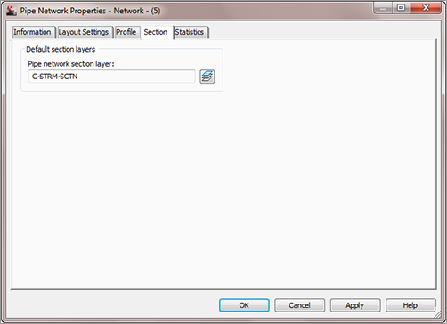
Section Here you can change the master object layers for network parts in a section (see Figure 13-31).
Figure 13-31: The Section tab of the Pipe Network Properties dialog
Statistics This tab gives you a snapshot of your pipe network information, such as elevation information, pipe and structure quantities, and references in use (see Figure 13-32).
Figure 13-32: The Statistics tab of the Pipe Network Properties dialog

The Select Surface tool on the Network Layout Tools toolbar allows you to switch between reference surfaces while you’re placing network parts. For example, if you’re about to place a structure that needs to reference the existing ground surface but your network surface was set to a proposed ground surface, you can click this tool to switch to the existing ground surface.
Using a Composite Finished Grade Surface for Your Pipe Network
It’s cumbersome to constantly switch between a patchwork of different reference surfaces while designing your pipe network. You may want to consider creating a finished grade-composite surface that includes components of your road design, finished grade, and even existing ground. You can create this finished grade-composite surface by pasting surfaces together, so it’s dynamic and changes as your design evolves.
The Select Alignment tool on the Network Layout Tools toolbar lets you switch between reference alignments while you’re placing network parts, similar to the Select Surface tool.
The Parts List tool allows you to switch parts lists for the pipe network.
The Structure drop-down list (see Figure 13-33a) lets you choose which structure you’d like to place next, and the Pipes drop-down list (see Figure 13-33b) allows you to choose which pipe you’d like to place next. Your choices come from the network parts list.
Figure 13-33:(a) The Structure drop-down list, and (b) the Pipes drop-down list

The options for the Draw Pipes and Structures category let you choose what type of parts you’d like to lay out next. You can choose Pipes and Structures, Pipes Only, or Structures Only.
Placing Parts in a Network
You place parts much as you do other Civil 3D objects or AutoCAD objects such as polylines. You can use your mouse, transparent commands, dynamic input, object snaps, and other drawing methods when laying out your pipe network.
If you choose Pipes and Structures, a structure is placed wherever you click, and the structures are joined by pipes. If you choose Structures Only, a structure is placed wherever you click, but the structures aren’t joined. If you choose Pipes Only, you can connect previously placed structures. If you have Pipes Only selected and there is no structure where you click, a null structure is placed to connect your pipes.
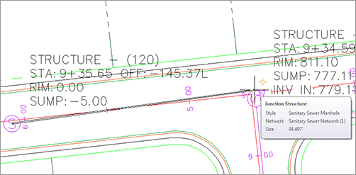
While you’re actively placing pipes and structures, you may want to connect to a previously placed part. For example, there may be a service or branch that connects into a structure along the main trunk. Begin placing the new branch. When you’re ready to tie into a structure, you get a circular connection marker (shown at the top of Figure 13-34) as your cursor comes within connecting distance of that structure. If you click to place your pipe when this marker is visible, a structure-to-pipe connection is formed (shown at the bottom of Figure 13-34).
Figure 13-34: The Structure Connection marker (top), and the Pipe Connection marker (bottom)

If you’re placing parts and you’d like to connect to a pipe, hover over the pipe you’d like to connect to until you see a connection marker that has two square shapes. Clicking to connect to the pipe breaks the pipe in two pieces and places a structure (or null structure) at the break point.
The Toggle Upslope/Downslope tool changes the flow direction of your pipes as they’re placed. In Figure 13-35, Structure 9 was placed before Structure 10.
Figure 13-35: Using (a) the Downslope toggle and (b) the Upslope toggle to create a pipe network leg
Optimizing the Cover by Starting Uphill
If you’re using the Cover and Slope rule for your pipe network, you’ll achieve better cover optimization if you begin your design at an upstream location and work your way down to the connection point.
The Cover and Slope rule prefers to hold minimum slope over optimal cover. In practice, this means that as long as minimum cover is satisfied, the pipe will remain at minimum slope. If you start your design from the upstream location, the pipe is forced to use a higher slope to achieve minimum cover. The following graphic shows a pipe run that was created starting from the upstream location (right to left):
When you start from the downhill side of your project, the Minimum Slope Rule is applied as long as minimum cover is achieved. The following graphic shows a pipe run that was created starting from the downstream location (left to right):
Notice how the slope remains constant even as the pipe cover increases. Maximum cover is a violation only rule, which means it never forces a pipe to increase slope to remain within tolerance; it only provides a warning that maximum cover has been violated.
Click Delete Pipe Network Object to delete pipes or structures of your choice. AutoCAD Erase can also delete network objects, but using it requires you to leave the Network Layout Tools toolbar.
Clicking Pipe Network Vistas brings up Panorama (see Figure 13-36), where you can make tabular edits to your pipe network while the Network Layout Tools toolbar is active.
Figure 13-36: Pipe Network Vistas via Panorama
The Pipe Network Vistas interface is similar to what you encounter in the Pipe Networks branch of Prospector. Many people think Pipe Network Vistas isn’t as user friendly as the Prospector interface because it doesn’t remember your preferred column order the way Prospector does. The advantage of using Pipe Network Vistas is that you can make tabular edits without leaving the Network Layout Tools toolbar. You can edit pipe properties, such as Invert and Slope, on the Pipes tab, and you can edit structure properties, such as Rim and Sump, on the Structure tab.
Creating a Sanitary Sewer Network
This exercise will apply the concepts taught in this section and give you hands-on experience using the Network Layout Tools toolbar:
1. Open Pipes-Exercise1.dwg, which you can download from www.sybex.com/go/masteringcivil3d2012.
2. Expand the Surfaces branch in Prospector. This drawing has several surfaces which have a _No Display style applied to simplify the drawing. Expand the Alignments and Centerline Alignments branches, and notice that there are several road alignments.
3. On the Home tab’s Create Design panel, select Pipe Network Pipe Network Creation Tools.
4. In the Create Pipe Network dialog (shown previously in Figure 13-26), give your network the following information:
- Network Name: Sanitary Sewer Network
- Network Description: Sanitary Sewer Network created by your name on today’s date
- Network Parts List: Sanitary Sewer
- Surface Name: Composite
- Alignment Name: Cabernet Court
- Structure Label Style: Data with Connected Pipes (Sanitary)
- Pipe Label Style: Length Description and Slope
5. Click OK. The Network Layout Tools toolbar appears.
6. Choose Concentric Structure 48 Dia 18 Frame 24 Cone from the drop-down list in the Structure menu and 8 Inch PVC from the Pipe list.
7. Click the Draw Pipes And Structures tool. Place two structures along Cabernet Court (the lower vertical road) somewhere between the road centerline and the right-of-way by selecting structure locations on your screen. (Doing so also places one pipe between the structures.) Note that the command line gives you additional options for placement. You can refer to the sections on pipe network creation and editing for additional methods of placement.
8. Without exiting the command, go back to the Network Layout Tools toolbar and change the Pipe drop-down from 8 Inch PVC to 10 Inch PVC and then place another structure. Notice that the diameter of the pipe between your second and third structures is 10″.
9. Press ↵ to exit the command.
10. Next, you’ll add a connecting length of pipe. Go back to the Network Layout Tools toolbar, and select 8 Inch PVC from the Pipe drop-down menu. Click the Draw Pipes And Structures tool button again. Add a structure off to one side of the road, and then connect to one of your structures within the road right-of-way. You’ll know you’re about to connect to a structure when you see the connection marker (a round, golden-colored glyph shaped like the one in Figure 13-37) appear next to your previously inserted structure.
Figure 13-37: The connection marker appears when your cursor is near the existing structure.
11. Press ↵ to exit the command. Observe your pipe network, including the labeling that automatically appeared as you drew the network.
12. Expand the Pipe Networks branch in Prospector in Toolspace, and locate your sanitary sewer network. Click the Pipes branch; the list of pipes appears in the preview pane. Click the Structures branch; the list of structures appears in the preview pane.
13. Experiment with tabular and graphical edits, drawing parts in profile view, and other tasks described throughout this chapter.
Creating a Storm Drainage Pipe Network from a Feature Line
If you already have an object in your drawing that represents a pipe network (such as a polyline, an alignment, or a feature line), you may be able to take advantage of the Create Pipe Network From Object command in the Pipe Network drop-down menu.
This option can be used for applications such as converting surveyed pipe runs into pipe networks and bringing forward legacy drawings that used AutoCAD linework to represent pipes. Because of some limitations described later in this section, it isn’t a good idea to use this in lieu of Create Pipe Network By Layout for new designs.
It’s often tempting in Civil 3D to rely on your former drawing habits and try to “convert” your AutoCAD objects into Civil 3D objects. You’ll find that the effort you spend learning Create Pipe Network By Layout pays off quickly with a better-quality model and easier revisions.
The Create Pipe Network From Object option creates a pipe for every linear segment of your object and places a structure at every vertex of your object. For example, the polyline with three line segments and three arcs, shown in Figure 13-38, is converted into a pipe network containing three straight pipes, three curved pipes, and seven structures—one at the start, one at the end, and one at each vertex.
Figure 13-38:(a) A polyline showing vertices, and (b) a pipe network created from the polyline
This option is most useful for creating pipe networks from long, single runs. It can’t build branching networks or append objects to a pipe network. For example, if you create a pipe network from one feature line and then, a few days later, receive a second feature line to add to that pipe network, you’ll have to use the pipe-network editing tools to trace your second feature line; no tool lets you add AutoCAD objects to an already-created pipe network.
This exercise will give you hands-on experience building a pipe network from a feature line with elevations:
1. Open the Pipes-Exercise2.dwg file. (It’s important to start with this drawing rather than use the drawing from an earlier exercise.)
2. Expand the Surfaces branch in Prospector. This drawing has several surfaces which have a _No Display style applied to simplify the drawing.
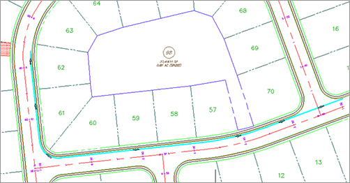
3. Expand the Alignments and Centerline Alignments branches, and notice that there are several road alignments. In the drawing, a cyan feature line runs through Syrah Way (the horizontal road) and then goes onto Frontenac Drive. This feature line represents utility information for a storm-drainage line. The elevations of this feature line correspond with centerline elevations that you’ll apply to your pipe network.
4. Choose Create Pipe Network From Object from the Pipe Network drop-down.
5. At the Select Object or [Xref]: prompt, select the cyan feature line. You’re given a preview (see Figure 13-39) of the pipe-flow direction that is based on the direction in which the feature line was originally drawn.
Figure 13-39: Flow-direction preview
6. At the Flow Direction [OK/Reverse] <Ok>: prompt, press ↵ to choose OK. The Create Pipe Network From Object dialog appears.
7. In the dialog, give your pipe network the following information:
- Network Name: Storm Network
- Network Description: Storm Network created by your name on today’s date from Feature Line
- Network Parts List: Storm Sewer
- Pipe To Create: 12 Inch Concrete Pipe
- Structure To Create: 15 x 15 Rect Structure 24 dia Frame
- Surface Name: Composite
- Alignment Name: <none>
- Erase Existing Entity check box: Selected
- Use Vertex Elevations check box: Selected
The two check boxes at the bottom of the dialog allow you to erase the existing entity and to apply the object’s vertex elevations to the new pipe network.
If you select Use Vertex Elevations, the pipe rules for your chosen parts list will be ignored. The elevations from each vertex will be applied as a center elevation of each pipe endpoint and not the invert as you may expect. For example, if you had a feature line that you created from survey shots of existing pipe inverts and used this method, your newly created pipe network would have inverts that were off by an elevation equal to the inner diameter of your newly created pipe.
8. Click OK. A pipe network is created.
If you do find that you’ve created a second network using this tool, you can actually merge them together. Simply select the newly created network, and from the Pipe Networks tab’s Modify panel, select Merge Networks. This will let you combine all your object-created networks into a more manageable single network.