
Once you know what parts you require, you need to investigate the part catalog to make sure these parts (or a reasonable approximation) are available.
The part catalog is a collection of two domains that contain two catalogs each. Structures are considered one domain, and Pipes are the second. The Structures domain consists of a Metric Structures catalog and a US Imperial Structures catalog; the Pipes domain consists of a Metric Pipes catalog and a US Imperial Pipes catalog.
Although you can access the parts from the catalogs while creating your parts lists in Civil 3D, you can’t examine or explore the catalogs easily while in the Civil 3D interface. It’s useful to understand where these catalogs reside and how they work.
The part catalog is installed locally by default at:
C:ProgramDataAutodeskC3D 2012enuPipes Catalog
Note that all paths in this chapter are the Windows 7 install paths. If you’re running Civil 3D on any other Windows operating systems, please check the Civil 3D Users Guide for information on the Pipes Catalog folder install location. Also, note that the ProgramData folder is hidden by default.
If you can’t locate the Pipes Catalog folder, it may be because your network administrator installed the catalogs at a network location when Civil 3D was deployed.
The Structures Domain
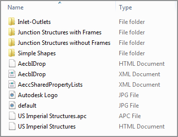
To learn more about how a catalog is organized, let’s explore the US Imperial Structures folder.
The first file of interest in the US Imperial Structures folder is an HTML document called US Imperial Structures (see Figure 13-4).
Figure 13-4: The US Imperial Structures HTML document
Double-click this file. Internet Explorer opens with a window so you can explore the US Imperial Structures catalog. A tree with different structure types on the left is under the Catalog tab. Expanding the tree allows you to explore the types of structures that are available. You may have to allow ActiveX controls to view the file.
Structures that fall into the same type have behavioral properties in common but may vary in shape and proportion. The four structure types in the default catalogs are as follows:
- Inlet-Outlets
- Junction Structures With Frames
- Junction Structures Without Frames
- Simple Shapes
Under each structure type are several shapes. The shape spells out the details of how the structure is shaped and proportioned, and it shows what happens to each dimension when the size increases. If you drill into the Junction Structures With Frames type and highlight the AeccStructConcentricCylinder_Imperial shape, you can see this in action (see Figure 13-5).
Figure 13-5: A closer look at the structure type and shape

In this view, you can see the available sizes of the concentric cylindrical structure, such as 48″ (121.92 cm), 60″ (152.40 cm), 72″ (182.88 cm), and 96″ (243.84 cm), but you may not edit them. Editing must be completed in the Part Builder, as discussed later in this chapter. Follow the table to see what happens to the cone height, wall thickness, floor thickness, and frame diameter and height as the diameter dimension increases. The structure may get bigger or smaller, but its basic form remains the same and its behavior is predictable.
Explore the other structures of the Junction Structures With Frames type, and note why they’re all considered to be the same type. Their shape changes, but their fundamental behavior and intent are similar. For example, each has a frame, each has a similar size range, and each is used as a junction for pipes.
Let’s return to the example of a sanitary sewer network. You need a standard concentric manhole and a simple, small-diameter cleanout, and most likely you have specification sheets from the concrete products company handy. You know that you’ll need to have a least a couple of junction structures, and based on the required structures’ spec sheets, you know you need a junction structure with frame. Your manhole most closely resembles the concentric cylindrical structure, and the 48″ (121.92 cm) and 60″ (152.40 cm) match the allowable sizes. For the cleanout, the cylindrical slab top structure is the appropriate shape and behavior, but you need a 6″ size. The smallest size available by default is 15″ (38.10 cm). Make notes on your checklist to add a part size for a 6″ (15.24 cm) cylindrical slab top structure. (You’ll take care of that in the next section.)
Something to keep in mind as you’re searching for the appropriate structures to meet your standard is that the part you choose doesn’t necessarily have to be a perfect match for your specified standard detail. The important things to look for are general shape, insertion behavior, and key dimensions.
Ask yourself the following questions:
- Will I be able to orient this structure in an appropriate way (is it round, rectangular, concentric, or eccentric)?
- Will I be able to label the insertion point (rim elevation) correctly?
- Will this structure look the way I need it to in the plan, profile, and section views? Does it look the same viewed from every angle, or would some views show a wider/narrower structure?
- Can I adjust my structure style in plan and profile views to display the structure the way I want to see it?
If you can find a standard shape that is conducive to all of these, it’s worth your time to try it out before resorting to building custom parts with Part Builder.
For example, if a certain catch basin required in your town has a unique frame and is an elongated rectangle, try one of the standard rectangle frame structures first (see Figure 13-6). You probably already use a certain type of block in your CAD drawings to represent this type of catch basin, and that block can be applied to the structure style. It’s not always necessary to build a custom part for small variations in shape. The important thing is that you model and label your rims and inverts properly. You’ll learn more about this in the next few sections.
Figure 13-6: Each catch basin can be modeled with the same rectangular slab top structure.
The Pipes Domain
The second part domain is named Pipes. Pipes have only one type, which is also called Pipes.
Locate the catalog HTML file under the US Imperial Pipes folder, and explore this catalog the same way you explored the US Imperial Structures catalog.
Double-click the HTML file. Internet Explorer opens with a window that allows you to view the US Imperial Pipes catalog. A tree with different pipe shapes appears on the left under the Catalog tab. Expanding the tree allows you to explore the pipe shapes that are available. Pipe shapes are broken into smaller categories by material (in the case of a circular pipe) or orientation (for an elliptical pipe).
The four pipe shapes in the default catalogs are as follows:
- Circular Pipes (Concrete, Ductile Iron, and Polyvinyl Chloride)
- Egg-Shaped Pipes (Concrete)
- Elliptical Pipes (Concrete Vertical and Concrete Horizontal)
- Rectangular Pipes (Concrete)
Drill into the Circular Pipes shape, and highlight the AeccCircularConcretePipe_Imperial material (see Figure 13-7). Let’s dig into this a bit more.
Figure 13-7: A closer look at the pipe shape and material
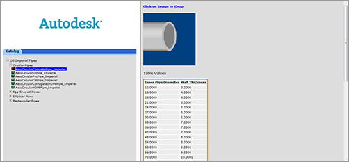
In this view, you can see the different inner pipe diameters and their corresponding wall thicknesses. Explore the other pipe shapes to get a feel for what is available.
You need 8″ (20.32 cm), 10″ (25.40 cm), and 12″ (30.48 cm) pipe for the sanitary sewer example. The spec sheet from the PVC pipe supplier indicates that the inner diameters and corresponding wall thicknesses are appropriate for your design.
Again, keep in mind as you’re searching for the appropriate pipes to meet your standard that the pipe you choose doesn’t necessarily have to be a perfect match for your specified standard detail. For example, your storm-drainage system might have the option to use high-density polyethylene (HDPE) pipe, and you might think you’d have to build a custom pipe type using Part Builder.
However, examine your symbology and labeling requirements a little further before jumping into building a custom part. The wall thickness of HDPE pipe is different from the same size PVC, but that may not be important for your drawing representation or labeling.
If you show HDPE as a single line or a double line representing inner diameter, wall thickness is irrelevant. You can create a custom label style to label the pipe HDPE instead of PVC.
If you show HDPE represented as its outer diameter or have particular requirements to show wall thickness in crossing and profile views, then building a custom pipe in Part Builder may be your best option (see Figure 13-8).
Figure 13-8: The top pipe must specify the outer diameter exactly. The bottom pipe, which uses a centerline to represent the inner diameter, doesn’t have this requirement.

The important things to consider are general shape and wall thickness. Ask yourself these questions:
- Does this pipe approximate the shape of my specified pipe?
- Does this pipe offer the correct inner diameter choice?
- How important is wall thickness to my model, plans, profiles, and sections?
- Can I adjust my pipe style in plan and profile views to display the pipe the way I need to see it?
- Can I create a pipe label that will label this pipe the way I need it labeled?
Again, if you can find a standard pipe that is conducive to all of these, it’s worth your time to try it before you resort to building custom pipes with Part Builder.
The Supporting Files
Each part family in the catalog has three corresponding files located at:
C:ProgramDataAutodeskC3D 2012enuPipes Catalog
Two files are mandatory sources of data required for the part to function properly, and one is an optional bitmap that provides the preview image you see in the catalog browser and parts-list interface.
First, dig into the US Imperial Pipes folder as follows:
C:ProgramDataAutodeskC3D 2012enuPipes CatalogUS Imperial
PipesCircular Pipes
This reveals the following files for the Imperial Circular Pipe:
partname.dwg This part drawing file contains the geometry that makes up the part as well as the definition of the parametric relationships.
partname.xml This part XML file is created as soon as a new part file is started in Part Builder. This file contains information on the parameter sizes, such as wall thickness, width, and diameter.
partname.bmp This part image file is used as a visual preview for that particular part in the HTML catalog (as you saw in the previous section). This file is optional.
You’ll study some of these files in greater detail later this chapter.
Mark on your checklist which parts you’d like to use from the standard catalog, and also note the parts that you may have to customize using Part Builder.