
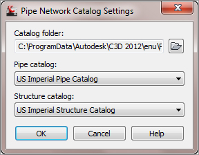
The Civil 3D pipe network catalogs are drawing-specific. If you’re in a metric drawing, you need to make sure the catalog is mapped to metric pipes and structures, whereas if you’re in an imperial drawing, you’ll want the imperial. By default, the Civil 3D templates should be appropriately mapped, but it’s worth the time to check. Set the catalog by changing to the Home tab and selecting the drop-down list on the Create Design panel. Verify the appropriate folder and catalog for your drawing units in the Pipe Network Catalog Settings dialog (see Figure 13-9), and you’re ready to go.
Figure 13-9: Choose the appropriate folder and catalog for your drawing units.
Understanding the Organization of Part Builder
The vocabulary used in the Part Builder interface is related to the vocabulary in the HTML catalog interface that you examined in the previous section, but there are several differences that are sometimes confusing.
To open Part Builder, select the drop-down list on the Create Design panel of the Home tab.
The first screen that appears when you start the Part Builder is Getting Started – Catalog Screen (see Figure 13-10).
Figure 13-10: The Getting Started – Catalog Screen

At the top of this window is a drop-down menu for selecting the pipe catalog. The choices, in this case Pipe and Structure, are based on what has been set for the drawing (either Metric or Imperial).
Below the Part Catalog input box is a listing of chapters. (In terms of Part Builder vocabulary, a pipe chapter is roughly equivalent to the catalog interface term shape.) The US Imperial Pipe Catalog has four default chapters: Circular Pipes, Egg-Shaped Pipes, Elliptical Pipes, and Rectangular Pipes. You can create new chapters for different-shaped pipes, such as Arch Pipe.
The US Imperial Structure Catalog also has four default chapters: Inlets-Outlets, Junction Structures With Frames, Junction Structures Without Frames, and Simple Shapes. You can create new chapters for custom structures. (In terms of Part Builder vocabulary, a structure chapter is roughly equivalent to the catalog interface term type.)
You can expand each chapter folder to reveal one or more part families. The US Imperial Circular Pipe Chapter has six default families (Concrete Pipe, Corrugated HDPE Pipe, Corrugated Metal Pipe, Ductile Iron Pipe, HDPE Pipe, and PVC Pipe). Pipes that reside in the same family typically have the same parametric behavior, with only differences in size.
The US Imperial Structure Catalog has four default chapters (Inlet-Outlets, Concentric Cylindrical Structure NF, Cylindrical Junction Structure NF, and Rectangular Junction Structure NF). Like pipes, structures that reside in the same family typically have the same parametric behavior, with only differences in size.
As Table 13-1 shows, a series of buttons on the Getting Started – Catalog Screen lets you perform various edits to chapters, families, and the catalog as a whole.
Table 13-1: The Part Builder Catalog Tools
| Icon | Function |

|
The New Parametric Part button creates a new part family. |

|
The Modify Part Sizes button allows you to edit the parameters for a specific part family. |

|
The Catalog Regen button refreshes all the supporting files in the catalog when you’ve finished making edits to the catalog. |

|
The Catalog Test button validates the parts in the catalog when you’ve finished making edits to the catalog. |

|
The New Chapter button creates a new chapter. |

|
The Delete button deletes a part family. Use this button with caution, and remember that if you accidentally delete a part family, you can restore your backup catalog as mentioned in the beginning of this section. |
Exploring Part Families
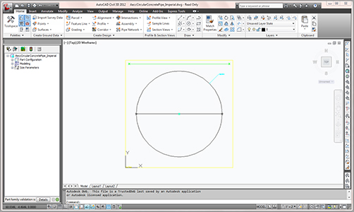
The best way to get oriented to the Part Builder interface is to explore one of the standard part families. In this case, click the Part Catalog drop-down list and select Pipe. Then drill down through the US Imperial Pipe Catalog Circular Pipe Chapter Concrete Pipe family by highlighting Concrete Pipe and clicking the Modify Part Sizes button. A Part Builder task pane appears with AeccCircularConcretePipe_Imperial.dwg on the screen, as shown in Figure 13-11.
Figure 13-11: The Parametric Building environment
You can close Part Builder by clicking on the X on the Part Builder palette. Click No when asked to save the changes to the Concrete Pipe. And click No when asked to save the drawing.
The Part Builder task pane, or Content Builder (Figure 13-12), is well documented in the Civil 3D User’s Guide. Please refer to the User’s Guide for detailed information about each entry in Content Builder.
Figure 13-12: Content Builder

Is That All There Is to Part Builder?
There is much more to Part Builder than this book can cover. As a matter of fact, a separate book could be written just on that subject. So if you are hungering for more information on Part Builder, we’d like to point you the website of Cyndy Davenport. Cyndy has been a repeat speaker at Autodesk University on Part Builder and Civil 3D. You can find her blog at http://c3dcougar.typepad.com/.
Adding a Part Size Using Part Builder
The hypothetical municipality requires a 12″ (30.48 cm) sanitary sewer cleanout. After studying the catalog, you decide that Concentric Cylindrical Structure With No Frames is the appropriate shape for your model, but the smallest inner diameter size in the catalog is 48″ (121.92 cm). The following tutorial gives you some practice in adding a structure size to the catalog—in this case, adding a 12″ (30.48 cm) structure to the US Imperial Structures catalog:
1. You can make changes to the US Imperial Structures catalog from any drawing that is mapped to that catalog, which is probably any imperial drawing you have open. For this exercise, start a new drawing from _AutoCAD Civil 3D (Imperial) NCS.dwt.
2. On the Home tab, select the drop-down list on the Create Design panel and select Part Builder.
3. Choose Structure from the drop-down list in the Part Catalog selection box.
4. Expand the Junction Structure Without Frames chapter.
5. Highlight the Concentric Cylindrical Structure NF (no frames) part family.
6. Click the Modify Part Sizes button.
7. The Part Builder interface opens AeccStructConcentricCylinderNF_Imperial.dwg along with the Content Builder task pane.
8. Expand the Size Parameters tree.
9. Right-click the SID (Structure Inner Diameter) parameter, and choose Edit. The Edit Part Sizes dialog appears.
10. Locate the SID column (see Figure 13-13). Double-click inside the box, and note that a drop-down menu shows the available inner diameter sizes: 48, 60, 72, and 96″ (121.92, 152.40, 182.88, and 243.84 cm).
Figure 13-13: Choosing a part size

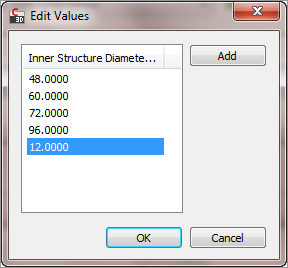
11. Locate the Edit button. Make sure you’re still active in the SID column cell, and then click Edit. The Edit Values dialog appears. Click Add, and type 12 (30.48 cm), as shown in Figure 13-14. Click OK to close the Edit Values dialog, and click OK again to close the Edit Part Sizes dialog.
Figure 13-14: Add the 12″ value to the Edit Values dialog
12. Click the small X in the upper-right corner of the Content Builder task pane to exit Part Builder. When prompted with Save Changes To Concentric Cylindrical Structure NF, click Yes. (You could also click Save in Content Builder to save the part and remain active in the Part Builder interface.)
13. You’re back in your original drawing. If you created a new parts list in any drawing that references the US Imperial Structures catalog, the 12″ (30.48 cm) structure would now be available for selection.
Sharing a Custom Part
You may find that you need to go beyond adding pipe and structure sizes to your catalog and build custom part families or even whole custom chapters. Perhaps instead of building them yourself, you’re able to acquire them from an outside source.
The following section can be used as a reference for adding a custom part to your catalog from an outside source, as well as sharing custom parts that you’ve created. The key to sharing a part is to locate the three files mentioned earlier.
Adding a custom part size to your catalog requires these steps:
1. Locate the partname.dwg, partname.xml, and (optionally) partname.bmp files of the part you’d like to obtain.
2. Make a copy of the partname.dwg, partname.xml, and (optionally) partname.bmp files.
3. Insert the partname.dwg, partname.xml, and (optionally) partname.bmp files in the correct folder of your catalog.
4. Run the partcatalogregen command in Civil 3D.
Adding an Arch Pipe to Your Part Catalog
This exercise will teach you how to add a premade custom part to your catalog:
1. You can make changes to the US Imperial Pipes catalog from any drawing that is mapped to that catalog, which is probably any imperial drawing you have open. For this exercise, start a new drawing from the _AutoCAD Civil 3D (Imperial) NCS.dwt file.
2. Create a new folder called Arch Pipes in your backup directory. Out of the box, it is located here:
C:ProgramDataAutodeskC3D 2012enuPipes CatalogUS Imperial Pipes
This directory should now include five folders: Arch Pipes, Circular Pipes, Egg-Shaped Pipes, Elliptical Pipes, and Rectangular Pipes.
3. Copy the Concrete Arch Pipe.dwg and Concrete Arch Pipe.xml files into the Arch Pipe folder. (Note that there is no optional bitmap for this custom pipe.)
4. Return to your drawing, and enter PARTCATALOGREGEN in the command line. Press P to regenerate the Pipe catalog, and then press ↵ to exit the command.
If you created a new parts list at this point in any drawing that references the US Imperial Pipes catalog, the arch pipe would be available for selection.
5. To confirm the addition of the new pipe shape to the catalog, locate the catalog HTML file at
C:ProgramDataAutodeskC3D 2012enuPipes CatalogUS Imperial
PipesImperial Pipes.htm
Explore the catalog as you did in the “The Part Catalog” section earlier.