
At the beginning of this chapter, you made notes about your hypothetical municipality having certain requirements for how structures and pipes behave—things like minimum slope, sump depths, and pipe-invert drops across structure. Depending on the type of network and the complexity of your design, there may be many different constraints on your design. Civil 3D allows you to establish structure and pipe rules that will assist in respecting these constraints during initial layout and edits. Some rules don’t change the pipes or structures during layout but provide a “violation only” check that you can view in Prospector.
Rules are separated into two categories—structure rules and pipe rules—and are collected in rule sets. You can then add these rule sets to specific parts in your parts list, which you’ll build at the end of this chapter.
Structure Rules
Structure rule sets are located on the Settings tab of Toolspace, under the Structure tree.
For a detailed breakdown of structure rules and how they’re applied, including images and illustrations, please see the Civil 3D Users Guide. This section will serve as a reference when you’re creating rules for your company standards.
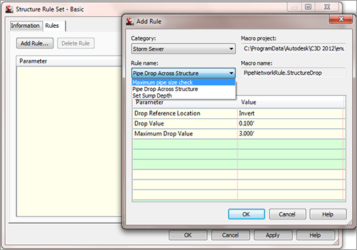
Under the Structure Rule Set tree, right-click Basic and click Edit. Click the Add Rule button on the Rules tab in the Structure Rule Set dialog. The Add Rule dialog appears, which allows you to access all the various structure rules (see Figure 13-15).
Figure 13-15: The Add Rule dialog
Maximum Pipe Size Check
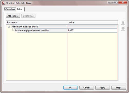
The Maximum Pipe Size Check rule (see Figure 13-16) examines all pipes connected to a structure and flags a violation in Prospector if any pipe is larger than your rule. This is a violation-only rule—it won’t change your pipe size automatically.
Figure 13-16: The Maximum Pipe Size Check rule option
Pipe Drop Across Structure
The Pipe Drop Across Structure rule (see Figure 13-17) tells any connected pipes how their inverts (or, alternatively, their crowns or centerlines) must relate to one another.
Figure 13-17: The Pipe Drop Across Structure rule options

When a new pipe is connected to a structure that has the Pipe Drop Across Structure rule applied, the following checks take place:
- A pipe drawn to be exiting a structure has an invert equal to or lower than the lowest pipe entering the structure.
- A pipe drawn to be entering a structure has an invert equal to or higher than the highest pipe exiting the structure.
- Any minimum specified drop distance is respected between the lowest entering pipe and the highest exiting pipe.
In the hypothetical sanitary sewer example, you’re required to maintain a 0.10′ invert drop across all structures. You’ll use this rule in your structure rule set in the next exercise.
Set Sump Depth
The Set Sump Depth rule (Figure 13-18) establishes a desired sump depth for structures. It’s important to add a sump-depth rule to all of your structure rule sets; otherwise, Civil 3D will assume a sump that is most often undesirable and is difficult to modify once your structures have been drawn.
Figure 13-18: The Set Sump Depth rule options
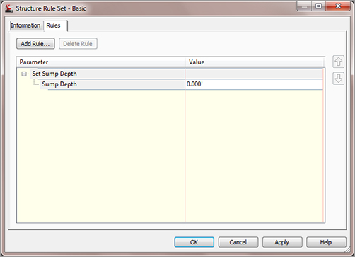
In the hypothetical sanitary sewer example, all the structures have a 1.5′ sump depth. You’ll use this rule in your structure rule set in the next exercise.
Pipe Rules
Pipe rule sets are located on the Settings tab of Toolspace, under the Pipe tree. For a detailed breakdown of pipe rules and how they’re applied, including images and illustrations, please see the Civil 3D Users Guide.
After you right-click on a Pipe Rule Set and click Edit, you can access all the pipe rules by clicking the Add Rule button on the Rules tab of the Pipe Rule Set dialog.
Cover and Slope Rule
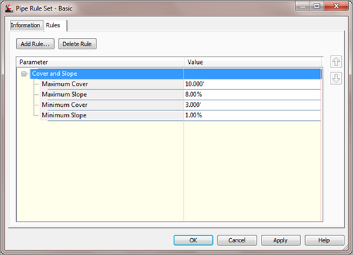
The Cover And Slope rule (Figure 13-19) allows you to specify your desired slope range and cover range. You’ll create one Cover And Slope rule for each size pipe in the hypothetical sanitary sewer example.
Figure 13-19: The Cover And Slope rule options
Cover Only Rule
The Cover Only rule (Figure 13-20) is designed for use with pressure-type pipe systems where slope can vary or isn’t a critical factor.
Figure 13-20: The Cover Only rule options

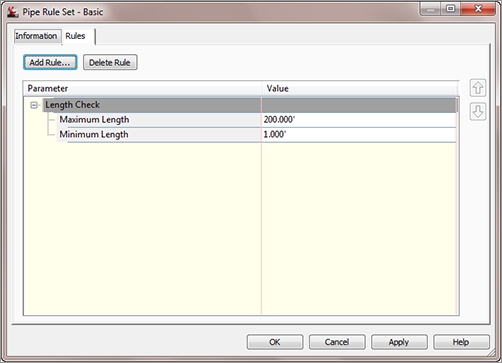
Length Check
Length Check is a violation-only rule; it won’t change your pipe length size automatically. The Length Check options (see Figure 13-21) allow you to specify a minimum and maximum pipe length.
Figure 13-21: The Length Check rule options
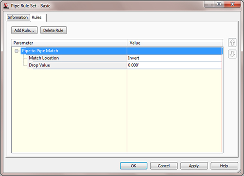
Pipe To Pipe Match Rule
The Pipe To Pipe Match rule (Figure 13-22) is also designed for use with pressure-type pipe systems where there are no true structures (only null structures), including situations where pipe is placed to break into an existing pipe. This rule determines how pipe inverts are assigned when two pipes come together, similar to the Pipe Drop Across Structure rule.
Figure 13-22: The Pipe To Pipe Match rule options
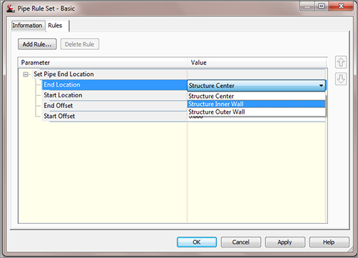
Set Pipe End Location Rule
The Set Pipe End Location rule (Figure 13-23) is new to Civil 3D 2012. It addresses an issue that has been plaguing engineers for some time. There is now the capability to set where the pipe end is located on the structure. You have the option of setting the start and end locations of the pipe to Structure Center (the way it has been), Structure Inner Wall, or Structure Outer Wall.
Figure 13-23: The Set Pipe End Location rule options
Creating Structure and Pipe Rule Sets
In this exercise, you’ll create one structure rule set and three pipe rule sets for a hypothetical sanitary sewer project:
1. Continue working in your drawing from the previous exercise.
2. Locate the Structure Rule Set on the Settings tab of Toolspace under the Structure tree. Right-click the Structure rule set, and choose New.
3. On the Information Tab, enter Sanitary Structure Rules in the Name text box.
4. Switch to the Rules tab. Click the Add Rule button.
5. In the Add Rule dialog, choose Pipe Drop Across Structure in the Rule Name drop-down list. Click OK. (You can’t change the parameters.)
6. Confirm that the parameters in the Structure Rule Set dialog are the following:
| Drop Reference Location | Invert |
| Drop Value | 0.1′ |
| Maximum Drop Value | 3′ |
These parameters establish a rule that will match your hypothetical municipality’s standard for the drop across sanitary sewer structures.
7. Click the Add Rule button.
8. In the Add Rule dialog, choose Set Sump Depth in the Rule Name drop-down list. Click OK. (You can’t change the parameters.)
9. Change the Sump Depth parameter to 1.5′ in the Structure Rule Set dialog to meet the hypothetical municipality’s standard for sump in sanitary sewer structures.
10. Click OK.
11. Locate the Pipe Rule Set on the Settings tab of Toolspace under the Pipe tree. Right-click the Pipe Rule Set, and choose New.
12. On the Information tab, enter 8 Inch Sanitary Pipe Rules for the name.
13. Switch to the Rules tab. Click Add Rule.
14. In the Add Rule dialog, choose Cover and Slope in the Rule Name drop-down list. Click OK. (You can’t change the parameters.)
15. Modify the parameters to match the constraints established by your hypothetical municipality for 8″ pipe, as follows:
| Maximum Cover | 10′ |
| Maximum Slope | 10% |
| Minimum Cover | 4′ |
| Minimum Slope | 0.40% |
16. Click OK.
17. Select the rule set you just created (8 Inch Sanitary Pipe Rules). Right-click, and choose Copy.
18. On the Information tab, enter 10 Inch Sanitary Pipe Rules in the Name text box.
19. Modify the parameters to match the constraints established by your hypothetical municipality for a 10″ pipe, as follows:
| Maximum Cover | 10′ |
| Maximum Slope | 10% |
| Minimum Cover | 4′ |
| Minimum Slope | 0.28% |
20. Repeat the process to create a rule set for the 12″ pipe using the following parameters:
| Maximum Cover | 10′ |
| Maximum Slope | 10% |
| Minimum Cover | 4′ |
| Minimum Slope | 0.22% |
21. You should now have one structure rule set and three pipe rule sets.
22. Save your drawing—you’ll use it in the next exercise.