Every subassembly is programmed to have certain capabilities, but it needs some guidance from the user to figure out exactly how to do what is wanted. For example, a daylight subassembly contains instructions for how it is to extend to a surface model, but it is up to you to tell it which surface model to work with. Many of the lane subassemblies can be used to hook into an offset alignment and/or profile, but need your help in determining which alignment and/or profile is desired.
These instructions to the subassembly are called targets. When you built the corridor in the first exercise, Civil 3D prompted you to add targets. In that case, you chose a surface target and continued. However, surface targets are just the tip of the iceberg.
Using Target Alignments and Profiles
So far, all of the corridor examples you looked at have a constant cross section. In the next section, we’ll take a look at what happens when a portion of your corridor needs to transition to a wider section and then transition back to normal.
Many subassemblies have been programmed to allow for not only a baseline attachment point but also additional attachment points on target alignments and/or profiles. Be sure to check the subassembly help file to make sure the subassembly you are using will accept targets if you need them. In Chapter 8, you learned that you can right-click on any subassembly to enter the help file. For instance, the BasicLane subassembly will show None in the Target Parameters area of the help file, but LaneOutsideSuper lists Width and Outside Elevation.
Think of a subassembly as a rubber band that is attached both to the baseline of the corridor (such as the road centerline) and the target alignment. As the target alignment, such as a lane widening, gets further from the baseline, the rubber band is stretched wider. As that target alignment transitions back toward the baseline, the rubber band changes to reflect a narrower cross section.
Figure 9-22 shows what happens to a cross section when various targets are set for the left edge of traveled way for a lane subassembly. Figure 9-22a shows the assembly as it was originally placed in the drawing. The width from the original assembly is 14′ with a cross slope of 2.00 percent to the edge of pavement. Figure 9-22b shows how the geometry changes if an alignment target is set for the edge of pavement. Notice that because there is no profile specified to change the elevation, the 2.00 percent cross slope is held and the lane width is the only geometry that changes. Figure 9-22c shows that if both an alignment and profile are specified for an edge of pavement alignment, the design cross slope and width both change. Lastly, you see the assembly with just a profile target assigned to the edge of pavement in Figure 9-22d. In this case, the width stays at 14′ but the elevation of the edge of pavement is dictated by the profile.
Figure 9-22: How geometry changes with a target on the left: Original assembly geometry (a), assembly with width alignment target only (b), assembly with both alignment and profile target (c), and assembly with only profile target set (d)
The following exercise shows you how to set targets using alignments and profiles for a corridor lane widening:
1. Open the Target Practice.dwg file. Note that this drawing has an incomplete corridor. You will be using the Target Mapping dialog to add the alignments and profiles that are created for you in this drawing.
2. Freeze the corridor using the Layer Freeze command from the Layers panel on the Home tab. Note that the Widening EOP alignment represents the edge of pavement (EOP) for a street parking zone (Figure 9-23).
Figure 9-23: Alignments in plan view that will be used in the exercise (rotated for illustration purposes)
3. Click the Layer Previous icon in the Layers panel to bring the corridor layer back.
4. Pan over to the cross-section view to the right in the drawing. Note the current cross slope and edge of pavement (EOP) offsets.
5. Pan to the profiles. The dark blue lines represent the EOP profile in the respective views. The light pink profile is the centerline profile superimposed for reference.
6. Pan back over to the corridor location. Select the corridor and click Corridor Properties from the context tab.
7. On the Parameters tab, scroll to the right until the ellipsis button for region RG - Urban 2x 14′ Lanes 2% Xslope - (3) target column is visible. Click the ellipsis button, as shown in Figure 9-24.
Figure 9-24: Click the ellipsis button to set targets for the region.
8. The Target Mapping dialog opens. Set the target surface to EG by clicking Click Here To Set All.
9. Click the Object Name field to the right of Width Alignment for Lane-Right. Highlight Cab Ct EOP-R alignment near the top of the Set Width Or Offset Target dialog. Click Add. Be sure the Cab Ct EOP-R appears in the listing near the bottom of the dialog, as shown in Figure 9-25. Click OK.
Figure 9-25: Highlight the alignment used as the width target and click Add.

10. Repeat step 9 for the Lane-Left width alignment. The alignment will be Cab Ct EOP-L.
11. Back in the Target Mapping dialog, scroll down to the Slope Or Elevation Targets area. Select the Object Name field next to Outside Elevation Profile for Lane-Right.
12. In the Set Slope Or Elevation Target dialog, select Cab Ct EOP-R from the Alignment drop-down.
13. Highlight Cab Ct EOP-R Prof from the listing and click Add. Verify that the profile has been added to the selected target listing (as shown in Figure 9-26) and click OK.
Figure 9-26: Set the alignment, and then highlight the profile used as the elevation target and click Add.

14. Repeat steps 12 and 13 for the Left EOP profile target. The profile name to be used is Cab Ct EOP-L Prof.
15. The Target Mapping dialog should now look like Figure 9-27. Click OK to dismiss the dialog.
Figure 9-27: Targets set for surface, width, and elevation for left and right sides

16. Click OK to dismiss the Corridor Properties dialog and allow the corridor to rebuild. The corridor should now be following the EOP alignments and resemble Figure 9-28.
Figure 9-28: The completed exercise in plan view (rotated for illustration purposes)

17. Pan over to reexamine the cross section. The section should now show that the targets, rather than the original assembly geometry, control the offset and elevations.
Corridor Properties Modifications Made Easy
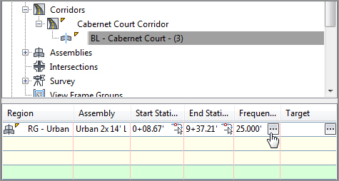
It can be tedious to modify alignments, profiles, starting stations, ending stations, frequencies, and targets along a corridor. Each of these items can be modified in the item view at the bottom (or side, depending on your orientation) of Prospector as shown here:
In the following quick exercise, you will use Toolspace to access and modify Frequency values for the Cabernet Court region:
1. Continue working in the Target Practice.dwg from the previous exercise. If you did not complete this exercise, you can use Target Practice - Complete.dwg.
2. In Prospector, expand the Cabernet Court Corridor and highlight BL - Cabernet Court - (3).
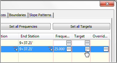
3. Select the Frequency ellipsis button from the Item view, as shown here:
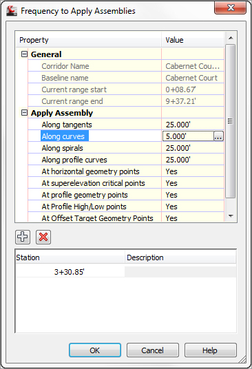
4. Set the Frequency Along Curves value to 5’.
5. Click the Plus sign to add a driveway station. At the Specify Station along Alignment: prompt, type 3+30.85. Press ↵ to accept the value, and then press ↵ again to return to the Frequency dialog box.
6. Click OK. The corridor will rebuild and the additional frequency lines should be visible in the plan.
Editing Sections
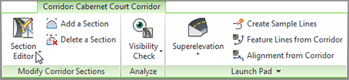
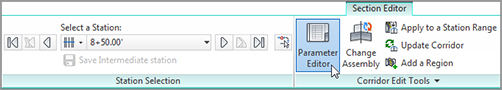
Once your corridor is built, chances are you will want to examine the corridor in section view, tweak a station here or there, and check for problems. For a station-by-station look at a corridor, pick the corridor and in the context tab, go to the Modify Corridor Sections panel and select Section Editor (see Figure 9-29).
Figure 9-29: Some of the many tools available on the Corridor context tab, including Section Editor
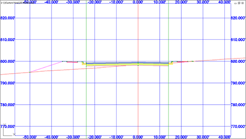
Once you are in the Section Editor, you are in a purely data-driven view. That means that this is a live, editable section of the corridor, and is not for plotting purposes (Figure 9-30).
Figure 9-30: The Corridor design in the Section Editor
The Station Selection panel on the Section Editor context tab allows you to move forward and backward through your corridor to see what each section looks like.
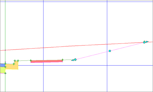
If you wish to edit a section, you may do so geometrically in the graphic or through the Parameter Editor palette, but not both. To graphically edit a link, hold down the Ctrl key on the keyboard while selecting the item. This will activate grips you can use to relocate or stretch the link (Figure 9-31).
Figure 9-31: A daylight link ready for grip-editing in the Section Editor
If you would rather use the Parameter Editor to make changes that are more precise to your section, select the Parameter Editor button from the Section Editor tab (Figure 9-32).
Figure 9-32: Some of the many tools from the Section Editor tab, including Parameter Editor
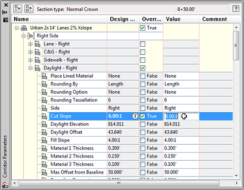
Look through the listing of subassemblies and their current values. When you find a value you wish to edit, click on the field to override the current value, as shown in Figure 9-33.
Figure 9-33: The corridor Parameter Editor
The changes you make can be applied to just the section you are viewing or to a range of stations in the region you are working in (use the Apply To A Station Range button in the Corridor edit tools to do so).
To exit the Section Editor, click the Close button on the Close panel.
Ack! Stuck in Bizzarro Coordinate System
If you accidentally exit your drawing without exiting the Section Editor, you will return to a drawing in a rotated coordinate system. It may be difficult to see your design, but don’t panic.
At the command line type Plan↵ W↵. You will see your project, but there is still another step.
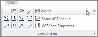
In the View tab, set the current UCS to World, as shown in the following graphic. The UCS icon will return to normal and you can continue working.