
Corridors are made up of several components. Marker points and links are coded into the subassemblies that comprise the assembly, as you saw in Chapter 8, “Assemblies and Subassemblies.” Feature lines glue the points and links together along the baseline.
First, let’s look at some important terminology you will want to become familiar with before proceeding. Baseline, regions, assemblies, frequency, and targets are all parts of a corridor that you will encounter even on your first design.
Baseline
The first ingredient in any corridor is an alignment. This alignment is referred to as a baseline. Every baseline alignment needs a corresponding design profile.
In this chapter, the baseline will correspond to the alignment and profile representing the crown of a road. However, this is not always the case, as we will explore in more depth in Chapter 10, “Advanced Corridors.” As your designs become more detailed, you will have corridors with multiple baselines.
Regions
When the geometry along a baseline changes enough to warrant a new assembly, a new region is needed. Regions specify the station range where a specific assembly is applied to the design. There may be many regions along a baseline to accommodate design geometry.
Regions must not overlap each other and must progress in ascending station values along the baseline.
Assemblies
You took a long, hard look at assemblies in Chapter 8. Figure 9-4 is a quick refresher on some of the terminology you encountered.
Figure 9-4: You will use these assembly parts to build a corridor.

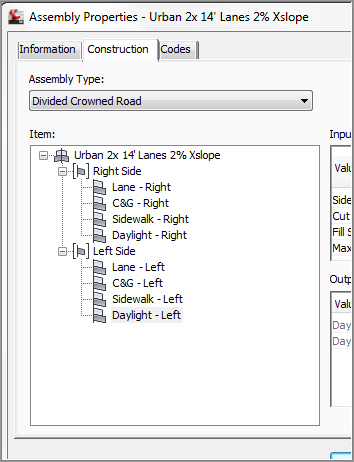
Remember, before you build a corridor it is a good idea to have your initial assemblies created. Don’t forget to give your subassemblies recognizable names (Figure 9-5).
Figure 9-5: Make corridor creation easier by giving recognizable names to subassemblies.
Frequency
Frequency refers to how often the assembly is applied to the corridor design. You can set the frequency distance for the corridor as a whole, but in most cases, you should apply it at the region level.
The frequency value will vary depending on the situation. The default frequencies are 25′ in Imperial units and a chunky 20 m for metric units. Civil 3D will place frequency lines at special stations such as superelevation key stations, horizontal design stations, and profile design stations. Users can create their own frequency stations for things like driveways or culvert crossings. Table 9-1 shows some typical frequencies for common design situations.
Table 9-1: Frequency guideline
| Design situation | Typical frequency |
| Civil 3D Default | 25′ (20 m) |
| Intersection Curb Return | 5′ (2 m) |
| Alignment Curve | 10′ (3 m) |
Corridor Feature Lines
After a corridor is created, you will see a series of lines running parallel (or mostly parallel) to the alignment; these lines are called corridor feature lines. Corridor feature lines, sometimes referred to simply as feature lines, are the result of Civil 3D playing connect-the-dots with marker points between the frequency lines.
Everywhere the assembly contains a named marker point, Civil 3D creates a feature line with the same name.
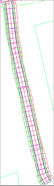
These special feature lines are the third dimension that takes a corridor from being simply a collection of cross sections to being a model with meaningful flow (see Figure 9-6).
Figure 9-6: The anatomy of a corridor
Later on in this chapter, we will take a closer look at corridor feature lines.
Create Simple Corridor vs. Create Corridor
On the Home tab, in the Create Design panel, the Corridor command has two options: Create Simple Corridor and Create Corridor. The only difference in the commands is what Civil 3D asks you to do along the way.

Create Simple Corridor has a step for naming the corridor right away, and presents you with the Target Mapping dialog before continuing with one initial region. Create Corridor assumes you’ve had your coffee for the day; you need to remember to name the corridor and set targets on your own. Create Corridor also allows you to add multiple regions on the first build.
At the end of each process, the result is identical: a corridor object to which you can add regions and baselines, and manipulate to your heart’s content.
This exercise gives you hands-on experience in building a corridor model from an alignment, a profile, and an assembly:
1. Open the Simple Corridor.dwg file, which you can download from www.sybex.com/go/masteringcivil3d2012. Note that the drawing has an alignment, a profile view with two profiles, and an assembly, as well as an existing ground surface.
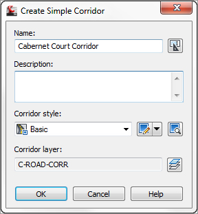
2. Change to the Home tab and select Corridor Create Simple Corridor from the Create Design panel. The Create Simple Corridor dialog opens.
3. In the Name text box, name the corridor Cabernet Court Corridor. Keep the default values for Corridor Style and Corridor Layer (see Figure 9-7).
Figure 9-7: Change the corridor name to something recognizable.
4. Click OK to dismiss the dialog and continue.
5. At the Select baseline alignment <or press enter key to select from list>: prompt, press ↵ and select the Cabernet Court alignment from the list. Click OK after highlighting Cabernet Court.
6. At the Select a profile <or press enter key to select from list>: prompt, pick the Finished Ground profile (the blue profile with labels) in the drawing. Alternatively, you could press ↵ and select your profile from a list.
7. At the Select an assembly <or press enter key to select from list>: prompt, pick the vertical line of the assembly in the drawing. Alternatively, you could press ↵ and select your assembly from a list.
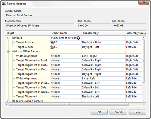
8. You are now shown the Target Mapping dialog for this corridor (Figure 9-8). Click the field that says <Click here to set all>. Highlight EG. Click OK to set the surface; then click OK to complete the corridor creation process.
Figure 9-8: Target Mapping dialog
9. You will receive several messages in Panorama, which read 0+00.00': Intersection with target could not be computed, Intersection Point doesn't exist, or something similar. You will rectify this issue in the following steps. Dismiss the Panorama. Your corridor should look like Figure 9-9.
Figure 9-9: The nearly completed corridor
Now, let’s try to figure out why we got those messages back in Panorama. In plan view, everything looks fine. However, a look at the corridor in the Object Viewer tells a different story (see Figure 9-10).
Figure 9-10: A “waterfall” at station 0+00

10. (Optional) If you’d like to view the corridor in the Object Viewer, select one of the corridor lines. Select Object Viewer from the context tab. Use the View Control drop-down from the top of the Object Viewer to show SW Isometric. After you have examined the corridor, dismiss the Object Viewer.

11. Select the corridor and click Corridor Properties from the context tab. In the Corridor Properties dialog, switch to the Parameters tab.
Notice in Figure 9-11 that the start station for the region is 0+00, which is coming from the alignment. However, the design profile begins at 0+08.6607. The difference in these values is causing the waterfall. To resolve this, tell the corridor not to start processing the region until the start of the design profile. Note that even though the display value shows only two decimal places, the corridor examines up to eight decimal places of precision. To make sure you are starting the region in the correct location, round up at the thousandths decimal place.
Figure 9-11: Corridor Properties dialog, Parameters tab
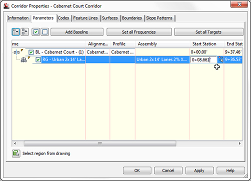
12. Click the Start Station field for the region and type 8.661. Station notation is not needed. Click OK to allow the corridor to reprocess. No errors will appear in Panorama.
A quick look in the Object Viewer should reveal that the waterfall is gone.
Rebuilding Your Corridor
A corridor is a dynamic model—which means that if you modify any of the objects used to create the corridor, the corridor must be updated to reflect those changes. For example, if you make a change to the Finished Ground profile, the corridor needs to be rebuilt to reflect the new design. The same principle applies to changes to alignments, assemblies, target surfaces, and any other corridor ingredients or parameters.
You can rebuild the corridor by selecting the corridor object graphically and choosing Rebuild from the context tab. You can also access the Rebuild command by right-clicking on the corridor name from Prospector, as shown in Figure 9-12.
Figure 9-12: Right-click the corridor name in the Corridor collection in Prospector to rebuild it.
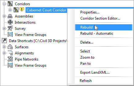
We recommend that you leave the option for Rebuild Automatic unchecked. Every time a change is made that affects your corridor, the corridor will go through the rebuilding process, during which you cannot work. The larger or more complex the corridor, the longer the rebuild process will take.
Troubleshooting Corridor Problems
Your corridor may not be perfect on your first iteration of the design. Get comfortable getting into and working with the Parameters tab of the Corridor Properties dialog. This tab will be your first stop to examine what might be amiss in your corridor model.
Whether you are building your first corridor or your five hundredth, odds are good that you will run into one of the following common issues:
Problem Your corridor seems to fall off a cliff, meaning the beginning or ending station of your corridor drops down to zero.
Typical Cause Your design profile starts and/or ends at a different station value than your alignment.
Fix This is exactly what we ran into in the first exercise. The corridor takes the initial station range from your alignment. However, most designers don’t tie into existing ground at the exact alignment start and end stations, so we need to adjust the corridor stations accordingly.
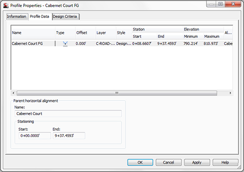
If you need to check the exact start and end stations of the design profile, the best place to do so is the Profile Data tab in Profile Properties dialog (as shown in Figure 9-13). Edit your corridor region to begin and end at the design profile station. To ensure you are within the design profile range, round up a smidgeon at the beginning (as we did in the exercise) and round down at the end.
Figure 9-13: Check your Profile Properties dialog to examine the station range of the design profile.
Alternately, you can use the station picker to select the first and last corridor region stations by snapping to the frequency lines that correspond to your profile geometry.
Problem Your corridor seems to take longer to build and has irregular frequency stations. Also, your daylighting may not extend out to where you expect it (see Figure 9-14).
Figure 9-14: An example of unexpected corridor frequency
Typical Cause You accidentally chose the Existing Ground profile instead of the Finished Ground profile for your baseline profile. Most corridors are set up to place a frequency line at every vertical geometry point, and a profile, such as the Existing Ground profile, has many more vertical geometry points than a layout profile (in this case, the Finished Ground profile). These additional points on the Existing Ground profile are the cause of the unexpected sample lines and flags that something is wrong.
Fix Always use care to choose the correct profile. Either physically pick the profile on screen or make sure your naming conventions clearly define your finished grade as finished grade. If your corridor is already built, pick your corridor, right-click, and choose Corridor Properties. On the Parameters tab of the Corridor Properties dialog, change the baseline profile from Existing Ground to Finished Ground. Figure 9-15 shows the Parameters tab with Finished Ground properly listed as the baseline profile.
Figure 9-15: Setting the design profile in the Parameters tab of the Corridor Properties dialog

Adding a surface target throws another variable into the mix. Here is a list of some of the most typical problems new users face and how to solve them:
Problem Your corridor doesn’t show daylighting even though you have a Daylight subassembly on your assembly. You may get a Target Object Not Found or a similar error message in Event Viewer.
Typical Cause You forgot to set the surface target when you created your surface.
Fix If your corridor is already built, pick your corridor, right-click, and select Corridor Properties. On the Parameters tab of the Corridor Properties dialog, click Set All Targets. The Target Mapping dialog opens, and its first entry is Surfaces. Click in the Object Name column field. This will prompt you to choose a surface for the Daylight subassembly to target.
Problem Your corridor seems to be missing patches of daylighting. You may also get an error message in Event Viewer.
Typical Cause Your target surface doesn’t fully extend the full length of your corridor or your target surface is too narrow at certain locations.
Fix Add more data to your target surface so that it is large enough to accommodate daylighting down the full length of the corridor. If this is not possible, omit daylighting through those specific stations, and once your corridor is built, do hand grading using feature lines or grading objects. You can also investigate other subassemblies such as Link Offset To Elevation that will meet your design intention without requiring a surface target.
Problem Your corridor daylighting falls short of a tie-in to the existing ground surface. You may get an error message in Event Viewer, such as No Intersection With Link Found.
Typical Cause Your Daylight subassembly parameters are too restrictive to grade all the way to your target surface. The Daylight link cannot find the target surface within the grade, width, or other parameters you’ve set in the subassembly properties.
Fix Revisit your Daylight subassembly settings to give the program a wider offset or steeper grade. If your settings cannot be adjusted, you’ll have to adjust your horizontal and/or vertical design to properly grade.