
Using Alignment and Profile Targets to Model a Roadside Swale
The previous chapter included an example where the road lane used an alignment and profile target to add a variable width and elevation to the edge of traveled way.
This chapter deals with a roadside swale that follows a variable horizontal alignment, as well as a vertical profile that doesn’t follow the centerline of the road. This happens frequently when existing culvert crossings must be met or when you have different slope requirements for the roadside swale.
Corridor Utilities
To create an alignment and profile for the swale, you’ll take advantage of some of the corridor utilities found in the Launch Pad panel (Figure 10-2) by selecting the corridor.
Figure 10-2: A bounty of corridor utilities on the Launch Pad panel

The utilities on this panel are as follows:
Superelevation This button will jump you to the alignment superelevation parameters. See Chapter 11, “Superelevation,” for a detailed look at how Civil 3D creates banked curves for your design speed.
Create Sample Lines Corridors and sample lines are both linked to alignments. Civil 3D gives you a shortcut to the sample line creation tool. Chapter 12, “Cross Sections and Mass Haul,” explores the creation and uses of sample lines.
Feature Lines From Corridor This utility extracts a grading feature line from a corridor feature line. This grading feature line can remain dynamic to the corridor, or it can be a static extraction. Typically, this extracted feature line will be used as a foundation for some feature-line grading or projection grading. If you choose to extract a dynamic feature line, it can’t be used as a corridor target due to possible circular references.
Alignments From Corridor This utility creates an alignment that follows the horizontal path of a corridor feature line. You can use this alignment to create target alignments, profile views, special labeling, or anything else for which a traditional alignment could be used. Extracted alignments are not dynamic to the corridor.
Profile From Corridor This utility creates a profile that follows the vertical path of a corridor feature line. This profile appears in Prospector under the baseline alignment and is drawn on any profile view that is associated with that baseline alignment. This profile is typically used to extract edge of pavement (EOP) or swale profiles for a finished profile view sheet or as a target profile for additional corridor design, as you’ll see in this section’s exercise. Extracted profiles aren’t dynamic to the corridor.
Points From Corridor This utility creates Civil 3D points that are based on corridor point codes. You select which point codes to use, as well as a range of corridor stations. A Civil 3D point is placed at every point-code location in that range. These points are a static extraction and don’t update if the corridor is edited. For example, if you extract COGO points from your corridor and then revise your baseline profile and rebuild your corridor, your COGO points won’t update to match the new corridor elevations.
Polyline From Corridor This utility extracts a 3D polyline from a corridor feature line. The extracted 3D polyline isn’t dynamic to the corridor. You can use this polyline as is or flatten it to create road linework.
The following exercise takes you through revising a model from a symmetrical corridor with roadside swales to a corridor with a transitioning roadside swale centerline. You’ll also take advantage of some of the static extraction corridor utilities discussed in this section:
1. Open the Corridor Swale.dwg file, which you can download from www.sybex.com/go/masteringcivil3d2012.
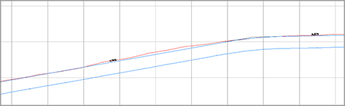
Note that the drawing contains a symmetrical corridor (see Figure 10-3), which was built using an assembly that includes two roadside swales. This drawing has been split into two modelspace views so you can see what is going on in plan and in profile at the same time.
Figure 10-3: The initial corridor with symmetrical roadside swales

2. Select the corridor, and choose the Alignment From Corridor tool from the Launch Pad panel. When prompted, pick the corridor feature line that represents the swale on the left side of the road centerline, as noted in the drawing, to create an alignment.
Note that if you select one of the corridor feature lines to activate the Corridors tab, that feature line will be created by default. You can pick one of the frequency lines to avoid this potential pitfall!
3. In the Create Alignment From Objects dialog (Figure 10-4), name the alignment Swale Left. Keep the default values for the Style and Label options as shown in Figure 10-4. Be sure to uncheck Create Profile. Click OK to finish. Press Esc to exit the command.
Figure 10-4: The Create Alignment From Objects dialog box appears when you’re extracting a feature line.

You should now have a new alignment with labels in the plan view, as shown in Figure 10-5.
Figure 10-5: The extracted alignment

Next, you will extract the profile in a separate step. By performing these actions in two steps, you ensure that the profile will be associated with the main alignment, rather than with the offset alignment you created in the previous step.
4. Select the Corridor and select Profile From Corridor from the Launch Pad panel of the contextual Ribbon tab.
5. Select the same Swale Left feature line as you did in the previous step. (You may need to use the DRAWORDER command to access the feature line hiding behind the new alignment.) When the feature line is selected, you will see the Create Profile dialog, as shown in Figure 10-6. Name the profile Swale Left Profile and click OK.
Figure 10-6: Create Profile dialog

6. You should now see the profile you just created in the bottom viewport. The profile represents the vertical path of the feature line representing the swale centerline, as shown in Figure 10-7.
Figure 10-7: A portion of the resulting extracted profile
7. Pan over to your newly extracted swale centerline alignment. Using the alignment geometry tools and transparent commands you learned in previous chapters, add a PI at Sta. 46+00, with an offset of 15′ to the left (Hint: -15) in plan.
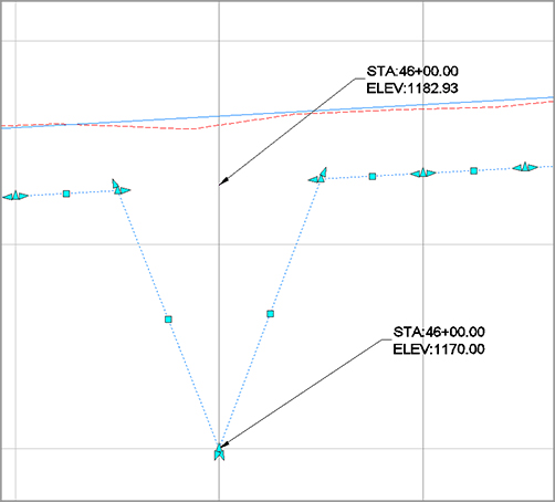
8. In the Profile view, grip-edit the swale centerline profile from 1182.93′ in elevation to elevation 1170′, as shown in Figure 10-8. Press Esc to exit the command.
Figure 10-8: Stretch a PVI to provide an exaggerated low spot.
9. Select the corridor and select Corridor Properties from the Modify panel to open the Corridor Properties dialog. Switch to the Parameters tab.
10. In the region, scroll over to the ellipsis button to open the Target Mapping dialog.
11. In the Width or Offset Target area (Figure 10-9), set the Foreslope - L subassembly to target the Swale Left Target Alignment.
Figure 10-9: Set the Foreslope - L subassembly to follow the Swale Left alignment and profile.
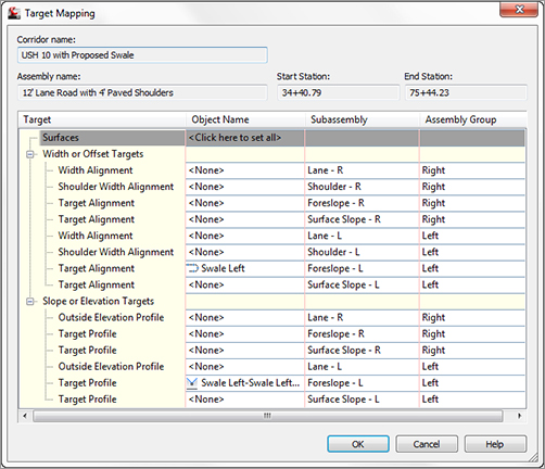
12. In the Slope or Elevation Targets area, set the Foreslope - L subassembly to target the Swale Left Profile. Figure 10-9 shows the Target Mapping dialog with the alignments and profiles appropriately mapped.
13. Click OK to dismiss the Target Mapping dialog. Click OK again to dismiss the Corridor Properties dialog and rebuild the corridor. When viewed in 3D, the corridor should now look like Figure 10-10.
Figure 10-10: The adjusted corridor
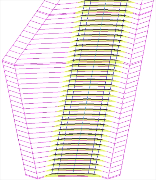
Note that the corridor has been adjusted to reflect the new target alignment and profile. Also note that you may want to increase the sampling frequency. You can view the sections using the View/Edit Corridor Section tools. You can also view the corridor in 3D by picking it, right-clicking, and choosing Object Viewer. Use the 3D Orbit tools to change your view of the corridor.