
Corridor feature lines are first drawn connecting the same point codes. For example, a feature line will work its way down the corridor and connect all the TopCurb points. If there are TopCurb points on the entire length of your corridor, then the feature line does not have any decisions to make. If your corridor changes from having a curb to having a grassed buffer or ditch, the feature line needs to figure out where to go next.
The Feature Lines tab of the Corridor Properties dialog has a drop-down menu called Branching (see Figure 9-16), with two options—Inward and Outward. Inward branching forces the feature line to connect to the next point it finds toward the baseline. Outward branching forces the feature line to connect to the next point it finds away from the baseline.
Figure 9-16: The Feature Lines tab of the Corridor Properties dialog

As mentioned earlier, a feature line will only connect the same point codes by default. However, the Feature Lines tab of the Corridor Properties dialog allows you to eliminate certain feature lines on the basis of the point code. For example, if for some reason you did not want your TopCurb points connected with a feature line, you could toggle that feature line off.
When a corridor is built, the feature line that is created is a similar type of object to the feature line you will use in Chapter 15, “Grading,” for grading purposes. The difference is that corridor feature lines are locked in the corridor object. There is not much we can do with them until they are extracted.
Corridor feature lines can be extracted from a corridor to produce alignments, profiles, and grading feature lines. Once an alignment or profile has been extracted, its geometry can be adjusted independently. In this case, the profile or alignment no longer retains a link to the corridor from which it originated. Once a profile or alignment has been extracted, you can use it as a target back in the corridor that formed it.
In the case of extracting a feature line, we have the choice of keeping the line dynamically linked to the corridor geometry or making it an entirely separate entity. If the feature line is linked, it can be used for grading and cannot be manipulated in any way other than modifying the corridor (i.e., it cannot be grip-edited). If the feature line is not linked, it can be used for grading or as a target in a corridor. The nonlinked feature line can be grip-edited and is completely divorced from the originating corridor. Both types of feature lines can be used as breaklines in surface models.
In the following exercise, a corridor feature line is extracted to produce an alignment and profile:
1. Open the Extract Feature Line.dwg file.
2. Change to the Home tab and select Alignment Create Alignment From Corridor from the Create Design panel.
3. Select the right edge of the corridor near the note in the drawing (the note is for reference only). This opens the Select A Feature Line dialog shown in Figure 9-17.
Figure 9-17: Selecting the Daylight feature line to be extracted as an alignment
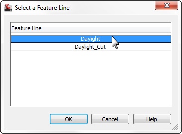
4. Select the Daylight feature line, as shown in Figure 9-17.
5. Click OK to close the Select A Feature Line dialog. The Create Alignment From Objects dialog is displayed, as shown in Figure 9-18.
Figure 9-18: The completed Create Alignments From Objects dialog
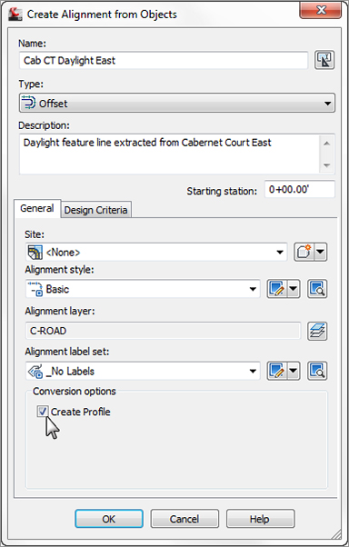
6. Change your options to match those shown in Figure 9-18. Notice that the Create Profile option has been selected.
7. Click OK to dismiss the Create Alignment From Objects dialog. The Create Profile – Draw New dialog opens, as shown in Figure 9-19.
Figure 9-19: The Create Profile – Draw New dialog
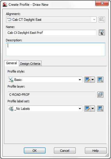
8. Change your options to match those shown in Figure 9-19.
9. Click OK to dismiss the dialog and then press ↵ to exit the command.
10. Review the alignment and profile as shown on the Prospector tab of Toolspace (see Figure 9-20).
Figure 9-20: A completed alignment and profile shown on the Prospector tab of Toolspace

11. Next, you will extract a corridor feature line and keep it dynamically linked to the corridor. From the Home tab, in the Create Design panel, select Feature Line From Corridor.
12. Select the feature line labeled in the drawing as Hinge. Verify Hinge when prompted to select a feature line in the Select A Feature Line dialog. Click OK.
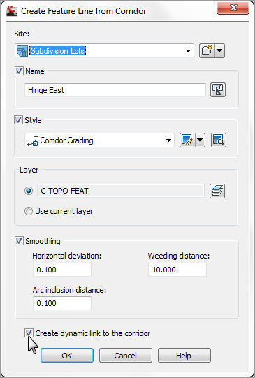
13. Select the Name check box and name the feature line Hinge East. Set this and all other settings to match Figure 9-21.
Figure 9-21: The Create Feature Line From Corridor dialog with the option to create a dynamic link turned on
14. Select the newly created feature line. Note that it can be selected but does not have grips. Take a look at the context tab and note which options are grayed out and which are not.