
Sample lines are the engine underneath both sections and materials and are held in a collection called sample line groups. One alignment can have multiple sample line groups, but a sample line group can sample only one alignment. Sample lines typically consist of two components: the sample lines and the sample line labels, as shown in Figure 12-3.
Figure 12-3: Sample lines consist of the lines and their labels.

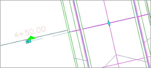
If you pick a sample line, you will see it has three different types of grips, as shown in Figure 12-4. The diamond grip on the alignment allows you to move the sample line along the alignment. The triangular grip on the end of the sample line allows you to move the sample line along an extension of the line, making it either longer or shorter. The square grip on the end of the sample line allows you to not only move the sample line in or out, but also move it in any direction on the XY-plane.
Figure 12-4: The three types of grips on a sample line
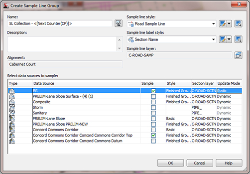
To create a sample line group, change to the Home tab and choose Sample Lines from the Profile & Section Views panel. After selecting the appropriate alignment, the Create Sample Line Group dialog shown in Figure 12-5 will display. This dialog prompts you to name the sample line group, apply a sample line and label style, and choose the objects in your drawing that you would like to sample. Every object that is available will be displayed in this box, with an area to set the section style, whether to sample the data, what layer each sampled item would be applied to, and a setting to specify whether the data should be static or dynamic. For example, you would typically select your existing ground (EG) surface to be sampled, displayed with an EG style, and be static. Your finished grade (FG) surface would also be sampled, but would be displayed with an FG style and be dynamic.
Figure 12-5: The Create Sample Line Group dialog
Once the sample data has been selected, the Sample Line Tools toolbar will appear, as shown in Figure 12-6. This toolbar is context-sensitive and is displayed only when you are creating sample lines.
Figure 12-6: The Sample Line Tools toolbar
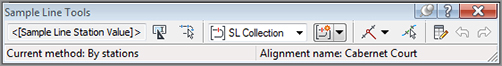
Once you have completed the Sample Line Creation process, close the toolbar, and the command ends. Because most of the information is already set for you in this toolbar, the Sample Line Creation Methods button is the only one that is really needed. This gives you the following five options for creating sample lines:
- By Range Of Stations
- At A Station
- From Corridor Stations
- Pick Points On Screen
- Select Existing Polylines
In Civil 3D, these options are listed in order from most used to least used. Because the most common method of creating sample lines is from one station to another at set intervals, the By Range Of Stations option is first. You can use At A Station to create one sample line at a specific station. From Corridor Stations allows you to insert a sample line at each corridor assembly insertion. Pick Points On Screen allows you to pick any two points to define a sample line. This option can be useful in special situations, such as sampling a pipe on a skew. The last option, Select Existing Polylines, lets you define sample lines from existing polylines.
A Warning About Using Polylines to Define Sample Lines
Be careful when picking existing polylines to define sample lines. Any osnaps used during polyline creation can throw off the Z-values of the section, sometimes giving undesirable results.
To define sample lines, you need to specify a few settings. Figure 12-7 shows the settings that need to be defined in the Create Sample Lines – By Station Range dialog. Right Swath Width is the width from the alignment that you sample. Most of the time this distance is greater than the ROW distance. You also select Sampling Increments, and choose whether to include special stations, such as horizontal geometry (PC, PT, and so on), vertical geometry (PVC, high point, low point, and so on), and superelevation critical stations.
Figure 12-7: Sample line settings

Creating Sample Lines along a Corridor
Before creating cross sections, you must sample the information that will be displayed. You do so by creating sample lines, which are part of a sample line group. Only one alignment can be sampled per sample line group. When creating sample lines, you will have to determine the frequency of your sections and the objects that you want included in the section views. In the following exercise, you create sample lines for Cabernet Court:
1. Open the sections1.dwg file, which you can download from www.sybex.com/go/masteringcivil3d2012.
2. Change to the Home tab and choose Sample Lines from the Profile & Section Views panel.
3. Press ↵ to display the Select Alignment dialog.
4. Select the Cabernet Court alignment and click OK. You can also pick the alignment in the drawing. The Create Sample Line Group dialog opens.
5. Adjust your settings to match those shown in Figure 12-8 and click OK.
Figure 12-8: Use these settings in the Create Sample Line Group dialog.

6. On the Sample Line Tools toolbar, click the Sample Line Creation Methods drop-down arrow and then select By Range Of Stations. Observe the settings but do not change anything.
7. Click OK, and press ↵ to end the command.
8. If you receive a Panorama view telling you that your corridor is out of date and may require rebuilding, dismiss it.
The sample lines can be edited by using the grips as just described or by selecting a sample line and choosing Edit Sample Line from the Modify panel. This command displays both the Sample Line Tools toolbar and the Edit Sample Line dialog, allowing you to pick your alignment. Once the alignment is picked, the sample lines can be edited individually or as a group. The Edit Sample Lines dialog allows you to pick a sample line and edit the information on an individual basis, but it is much more efficient to edit all the sample lines at the same time.
Editing the Swath Width of a Sample Line Group
There may come a time when you will need to show information outside the limits of your section views or not show as much information. To edit the width of a section view, you will have to change the swath width of a sample line group. These sample lines can be edited manually on an individual basis, or you can edit the entire group at once. In this exercise, you edit the widths of an entire sample line group:
1. Continue working on sections1.dwg, or you can open the sections2.dwg file.
2. Select a sample line and choose Edit Sample Line from the Modify panel. The Sample Line Tools toolbar and the Edit Sample Line dialog appear.
3. Click the down arrow for the sample line editing tools on the toolbar and then click the Edit Swath Widths For Group button. The Edit Sample Line Widths dialog appears.
4. Type 100 in both the Left and Right Swath Width text boxes. Click OK.
5. Press ↵ to end the command.
6. If you receive a Panorama view telling you that your corridor is out of date and may require rebuilding, dismiss it.
7. Examine your sample lines, noting the wider sample lines.