
Even if you never plan to build one in real life, understanding what is going on in a cul-de-sac corridor model will set you on the right path for building more complex models. If you truly understand the principles explained in the section that follows, then expanding your repertoire to include intersections and roundabouts will become much easier.
Using Multiple Baselines
Up to this point, every corridor we’ve examined has had a single baseline. In our examples, the centerline alignment has been the main driving force behind the corridor design. In this section, the training wheels are coming off! You’ve seen the last of single baseline corridors in this book.
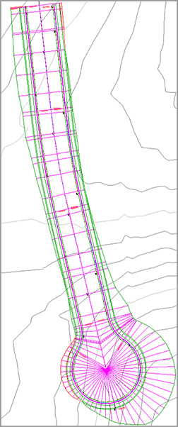
A cul-de-sac by itself can be modeled in two baselines, as shown in Figure 10-15. The procedures that follow will work for most cul-de-sacs, symmetrical, asymmetrical, and hammerhead styles. You will need the centerline alignment and design profile, as well as an edge of pavement alignment and design profile.
Figure 10-15: Example cul-de-sac alignment setup
In the section leading to the cul-de-sac bulb, the corridor can be modeled using the tools you learned in Chapter 9. From station 0+00 to 1+50, the centerline of the road is the baseline, with an assembly using two lanes and with the crown as the baseline marker. However, once the curvature of the bulb starts at 1+50.00, the centerline is no longer an acceptable baseline.
Assemblies are always applied perpendicular to a baseline. To get correct pavement grades in the bulb, you’ll need to hop over to the edge of pavement alignment for a baseline. This second baseline will use a partial assembly that is built with the main assembly marker at the outside edge of pavement (Figure 10-16). The crown of the road will stretch to meet the centerline alignment and profile as its targets.
Figure 10-16: Assembly used for designing off the edge of pavement

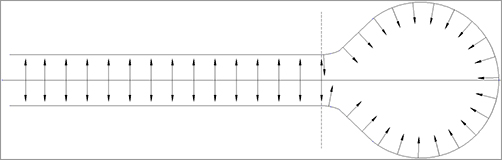
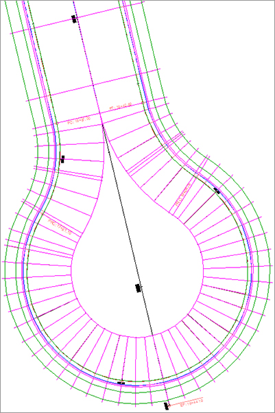
It helps to think of the assembly as radiating away from the baseline, from the assembly base outward, toward a target (Figure 10-17). Because the assemblies are applied to the baseline in a perpendicular manner, using the edge of pavement for a baseline in curved areas (such as cul-de-sac bulbs or curb returns) will result in a smooth, properly graded pavement surface.
Figure 10-17: It helps to think of the assemblies radiating away from the baseline toward the targets.
Establishing EOP Design Profiles
One of the most challenging parts of any “fancy” corridor (i.e., cul-de-sac, intersection, or roundabout) is establishing design profiles for noncenterline alignments. You must have design profiles for every alignment used as a target—there’s no way around it—but it does not have to be a painful process to obtain them.
Using a simple, preliminary corridor and the profile creation tools you learned in Chapter 7, “Profiles and Profile Views,” establishing an edge of pavement (EOP) profile can go quickly.
In the exercise that follows, you will work through the steps of creating an EOP profile:
1. Open the Cul-de-sac_Profile.dwg file, which you can download from this book’s web page.
This drawing contains several alignments and an existing surface that is turned off.
2. From the Home tab, click Corridor Create Simple Corridor. Name the corridor PRELIM. Click OK.
3. Click the centerline near the cul-de-sac bulb, Frontenac Drive. For the profile, use Frontenac Drive - FG. For assembly, use PRELIM.
4. No targets are needed in this preliminary corridor, so click OK to complete the corridor.
5. Select the new corridor and open Corridor Properties. On the Surfaces tab, click the leftmost button to start a corridor surface. With Data Type set to Links and Code set to Top, click Add.
6. On the Boundaries tab, right-click the PRELIM Surface, click Add Automatically, and use ETW as the outer boundary. Click OK.
7. You should now see contours in your drawing representing the 2 percent crossfall from the centerline. Select the red EOP alignment for the cul-de-sac. In the contextual Ribbon tab, click Surface Profile.
8. In the Create Profile From Surface dialog, highlight PRELIM Surface and click Add. Click the Draw In Profile View button.
9. Leave all the defaults in the Create Profile View dialog and click Create Profile View. Click in the graphic to the right of the surface to place the view.
The profile you are seeing will have gaps in the middle that need grading information. However, the bulb portion of the profile only needs to exist between 16+87.00 and 19+42.89. They are the PC and PT stations for the EOP alignment in plan.
10. Select the profile view and click Profile Creation Tools on the contextual Ribbon tab. Click OK to accept the defaults in the Create Profile dialog.
11. In the Profile Layout toolbar, select Draw Tangents. Snap to the intersection of the preliminary profile and the grid line at 16+50. Next, snap to the endpoint where the preliminary surface trails off at station 17+05.88 (elevation 792.74). The next VPI will be the peak of the preliminary profile in the center of the view (station 18+14.94, elevation 790.35).
Snap to the endpoint where the preliminary profile picks up again (station 19+24.01, elevation 792.74). Finally, snap to the grade break at station 19+78.23, elevation 794.68.
12. Press ↵ to complete the command.
You now have a proposed profile that is acceptable to use in the cul-de-sac corridor.
Putting the Pieces Together
You have all the pieces in place to perform the first iterations of this cul-de-sac design.
The following exercise will walk you through the steps to put the cul-de-sac together. You will complete several steps and let the corridor build to observe what is happening at each stage. This exercise will also encourage you to get comfortable using Corridor Properties to make design modifications.
1. Open the Cul-de-sac_Design.dwg file, which you can download from this book’s web page. This drawing contains the cul-de-sac centerline alignment and profile, the EOP alignment and profile, and the assemblies needed to complete the process. The PRELIM corridor layer is frozen.
2. From the Home tab, on the Create Design panel select Corridor Create Corridor. Select the Frontenac Drive centerline alignment, the Frontenac Drive FG profile, and the Urban 2×14′ Lanes 2% Xslope assembly.
3. In the Create Corridor dialog, name the corridor Cul-de-Sac.
4. Click the Pick Station button for the start station of the first region. Snap to the start of the EOP alignment on the west side, as shown in Figure 10-18 (left). This will result in a start station of 11+42.86 in the Create Corridor dialog.
Figure 10-18: Setting the start station (left) and end station (right) for the centerline region
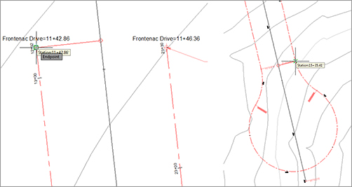
5. Click the Pick Station icon for the end station of the first region. Snap to the PT station on the east side of the cul-de-sac bulb, as shown in Figure 10-18 (right). This will result in the region end station of 15+35.41.
6. Scroll over and click the Target ellipsis. Set the surface target to EG. Click OK to dismiss the Target Mapping dialog. Click OK to let the corridor build.
Examine the corridor you just created. It should start south of the intersection with the Syrah Way alignment and end before the curvy part of the cul-de-sac bulb.
7. Select the corridor and click Corridor Properties. If necessary, correct any station problems with the first region.
8. In the Parameters tab of Corridor Properties, click Add Baseline. Select the Cul-de-Sac EOP as the alignment. Click OK.
9. In the Profile Column, click <Click here…>. Select the Cul-de-Sac EOP - FG profile (this is the profile that you learned how to develop in the previous exercise).
10. Right-click on the newly added baseline and select Add Region, as shown in Figure 10-19. Select the Curb Right assembly and click OK.
Figure 10-19: Right-click the baseline to add a region.

11. Click the Pick Station button for the Curb Right region start station. Select the PC station of the corridor bulb. This will result in a start station value of 16+87.00. Click the Pick Station icon for the end station of the region. Select the PT station of the corridor bulb. This will result in an end station of 19+42.89. Click OK and let the corridor build once again.
Have a look at the corridor in its current state (see Figure 10-20). Even if you are not exactly sure what you are looking at, you should at least see a few things are amiss with the corridor so far.
Figure 10-20: The cul-de-sac corridor several steps away from completion
There are three things that need to be modified before the cul-de-sac is complete. The lane needs to extend to the center of the cul-de-sac bulb and the daylight surface needs to be set, both of which can be corrected in the Target Mapping area. Finally, you will want to increase the frequency around the curvy area to get a smoother, more precise design.
In the next steps, you will correct these issues and complete the cul-de-sac.
12. Select the corridor and return to Corridor Properties (last time in this exercise, I promise). Scroll over, and click the ellipsis to enter the Target Mapping dialog for the region named RG - Curb Right - (36). (The number following the region name may vary.)
13. Set Target Surface to EG. Set Width Alignment for Lane - L to Frontenac Drive. Set Outside Elevation Profile to Frontenac Drive FG for Lane - L. Click OK.
14. Click the frequency ellipsis next to the current value of 25′ . Set the frequency for both tangents and curves to 5′ . Click OK to dismiss the Frequency dialog.
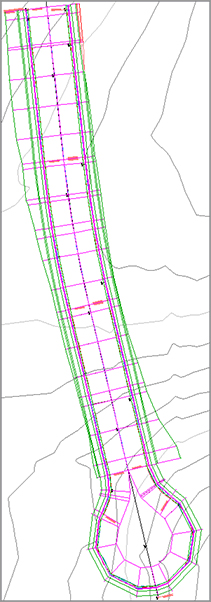
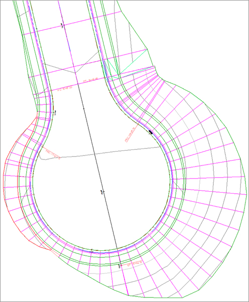
15. Click OK and let the corridor build one last time. The completed corridor will look like Figure 10-21.
Figure 10-21: The completed cul-de-sac corridor. Gorgeous!
Troubleshooting Your Cul-de-Sac
People make several common mistakes when modeling their first few cul-de-sacs:
Your cul-de-sac appears with a large gap in the center. If your curb line seems to be modeling correctly but your lanes are leaving a large empty area in the middle (see Figure 10-22), chances are pretty good that you forgot to assign targets or perhaps assigned the incorrect targets.
Figure 10-22: A cul-de-sac without targets
Fix this problem by opening the Target Mapping dialog for your region and checking to make sure you assigned the road centerline alignment and FG profile for your transition lane. If you have a more advanced lane subassembly, you may have accidentally set the targets for another subassembly somewhere in your corridor instead of the lane for the cul-de-sac transition, especially if you have poor subassembly-naming conventions. Poor naming conventions become especially confusing if you used the Map All Targets button.
Your cul-de-sac appears to be backward. Occasionally, you may find that your lanes wind up on the wrong side of the EOP alignment, as shown in Figure 10-23. The direction of your alignment will dictate whether the lane will be on the left or right side. In the example from the previous exercise, the alignment was running counterclockwise around the cul-de-sac bulb; therefore, the lane was on the left side of the assembly.
Figure 10-23: A cul-de-sac with the lanes modeled on the wrong side without targets (left) and with targets (right)

You can fix this problem by changing the assembly to the correct side.
Your cul-de-sac drops down to 0. A common problem when you first begin modeling cul-de-sacs, intersections, and other corridor components is that one end of your baseline drops down to 0. You probably won’t notice the problem in plan view, but once you build your surface (see Figure 10-24, left) or rotate your corridor in 3D (see Figure 10-24, right), you’ll see it. This problem will always occur if your region station range extends beyond the proposed profile.
Figure 10-24:(Right) Contours indicating that the corridor surface drops down to 0, and (left) a corridor viewed in 3D showing a drop down to 0

The fix for this is the same as what you saw in the first exercise in Chapter 9—that is, make sure your region station range jives with the design profile length. You may need to extend the design profile in some cases, but usually the station range will do the trick.
Your cul-de-sac seems flat. When you’re first learning the concept of targets, it’s easy to mix up baseline alignments and target alignments. In the beginning, you may accidentally choose your EOP alignment as a target instead of the road centerline. If this happens, your cul-de-sac will look similar to Figure 10-25.
Figure 10-25: A flat cul-de-sac with the wrong lane target set
You can fix this problem by opening the Target Mapping dialog for this region and making sure the target alignment is set to the road centerline and the target profile is set to the road centerline FG profile.