
Once you have a list of items that should be accounted for within your project, you have to assign them to items in your drawing file. You can do this in any of the following ways:
- Assign pay items to simple items like blocks and lines.
- Assign pay items to corridor components.
- Assign pay items to pipe network pipes and structures.
In the next few sections, you’ll explore each of these methods, along with some formula tools that can be used to convert things such as linear items to individual quantity counts.
AutoCAD Objects as Pay Items
The most basic use of the QTO tools is to assign pay items to things like blocks and linework within your drawing file. The QTO tools can be used to quantify tree plantings, signposts, or area items such as clearing and grubbing. In the following exercise, you’ll assign pay items to blocks as well as to some closed polylines. Be sure the Getting Started.csv and Getting Started Categories.xml files are loaded as described in the first exercise.
1. Open the Acad Objects in QTO.dwg file.
2. From the Analyze tab’s QTO panel, select QTO Manager to display the QTO Manager palette if it is not already open.
3. Expand the Favorites branch, right-click on CLEARING AND GRUBBING, and select Assign Pay Item To Area, as shown in Figure 18-6.
Figure 18-6: Assigning an area-based pay item

4. Enter O at the command line and press ↵ to activate the Object option for assignment.
5. Click on the outer edge of the site, as shown in Figure 18-7. Notice the entire polyline highlights to indicate what object is being picked. The command line should also echo Pay item 20101-0000 assigned to object when you pick the polyline. Note that this will create a hatch object reflecting the area being assigned to the pay item.
Figure 18-7: Selecting a closed polyline for an area-based quantity
6. Press ↵ again to complete the selection.
7. Move the QTO Manager palette to the side and zoom in on an area of the road where you can see two or more of the blocks representing trees.
8. Select one of the tree blocks. To select all of the tree blocks in the drawing, right-click and pick Select Similar.
9. Back on the QTO Manager palette, under the Favorites branch, select 62606-0150 FAGUS GRANDIFLORA, AMERICAN BEECH.
10. Near the top of the palette, click the Assign Pay Item button. Notice the great tooltips on these buttons.
11. Press ↵ to complete the assigning.
12. Repeat steps 9–11 to assign pay items to the fire hydrant blocks in the road right of way areas.
The two assignment methods shown here are essentially interchangeable. Pay items can be assigned to any number of AutoCAD objects, meaning you don’t have to redraw the planners’ or landscape architects’ work in Civil 3D to use the QTO tools.
Keep in mind that the pay item tag is saved with the block. This is a good thing if you assign a pay item to a block and copy the block because the copies will be automatically tagged. If you assign a pay item to an object and use the WBLOCK command to copy that object out of your current drawing and into another, the pay item assignment goes along as well. You’ll find out how to unassign pay items after we discuss all the ways to assign them.
Pricing Your Corridor
The corridor functionality of Civil 3D is invaluable. You can use it to model everything from streams to parking lots to roads. With the QTO tools, you can also use the corridor object to quantify much of the project construction costs.
Assemblies and QTO Are Related
Be mindful of what parts of an assembly are available when creating quantity takeoff assignments in the code set style.
If you plan to price an item based on the centerline of your road, make sure you have set Crown Point On Inside to Yes in the lane subassembly properties.

Changes to QTO information will not cause your corridor to flag itself as out of date. Before you run a takeoff report, it is a good idea to rebuild your corridor to ensure the most up-to-date information is accounted for.
In this first example, you’ll use the pay item list along with a formula to convert the linear curb measurement to an incremental count of light poles required for the project:
1. Open the Corridor Objects in QTO.dwg file.
2. From the Analyze tab’s QTO panel, select QTO Manager to display the palette.
3. Expand the Favorites branch to display your 63620-0500 light standard pay item.
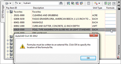
4. Scroll to the right to the Formula column and click in the empty cell on the Luminaire row. When you do, Civil 3D will display the alert box shown in Figure 18-8, which warns you that formulas must be stored to an external file.
Figure 18-8: Click in the Formula cell to display this warning dialog.
5. Click OK to dismiss the warning, and Civil 3D will present the Select A Quantity Takeoff Formula File dialog. Navigate to your desktop, change the filename to Mastering, and click the Save button to dismiss this dialog.
Civil 3D will display the Pay Item Formula: 63620-0500 dialog, as shown in Figure 18-9. (The expression will be empty when you first open it, but you’ll take care of that in the next steps.)
Figure 18-9: The completed pay item expression
Assume that you need a street light every 300 feet, but only on one side of the street. To do this, you add up all the lengths of curb, and then divide by 2 because you want only one half of the street to have lights. You then divide by 300 because you are running lights in an interval. Finally, you truncate and add 1 to make the number conservative.
6. Enter the formula using the buttons in the dialog or type it in to arrive at Figure 18-9; then click OK to dismiss the dialog. Note that the pay item list now shows a small calculator icon on that row to indicate a formula is in use.
Now that you’ve modified the way the light poles will be quantified from your model, you can assign the pay items for light poles and road striping to your corridor object. This is done by modifying the code set, as you’ll see in the next steps.
7. In the Toolspace Settings tab, select General Multipurpose Styles Code Set Styles All Codes. Right-click and select Edit to display the Code Set Style – All Codes dialog.
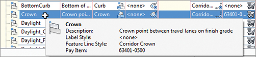
8. Change to the Codes tab, scroll down to the Point section, and find the row for Crown, as shown in Figure 18-10.
Figure 18-10: Select the Crown row in the Point section in the Code Set Style – All Codes dialog.
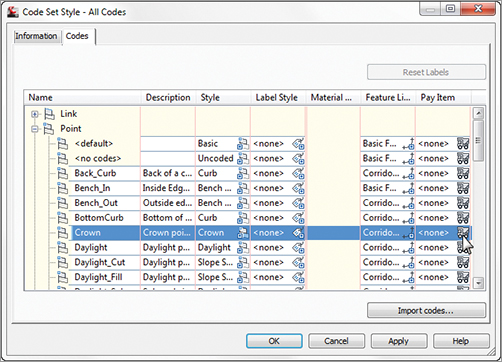
9. Click the truck icon in the Pay Item column, as shown in Figure 18-10, to open the Pay Item List dialog.
10. Expand the Favorites branch and select PAVEMENT MARKINGS, TYPE C, SOLID. Click OK to return to the Code Set Style – All Codes dialog. Your dialog should now reflect the pay item number of 63401-0500, as shown in Figure 18-11. Note that the tooltip also reflects this pay item.
Figure 18-11: Crown point codes assigned a pavement marking pay item
11. Find Back_Curb (which should be listed in the same area several rows above Crown), and repeat steps 9 and 10 to assign 63620-0500 to the Back_Curb code. Remember, this is your light standard pay item with the formula from the previous steps. Your dialog should look like Figure 18-12.
Figure 18-12: Completed code set editing for pay items

12. Switch to Prospector, and expand the Corridor branch. Right-click Main Corridor and select Properties to open the Corridor Properties dialog.
13. Change to the Codes tab and scroll down to the Point section. Notice that Back_Curb and Crown codes reflect pay items in the far-right column.
14. Click OK to close the dialog.
Best Practice: Storing a Formula File with the Project Files
Every drawing in which you utilize QTO tools is intended to have its own, unique formula file. We recommend that when you create a new formula file, you store it in the same folder as the rest of the project.
If you ever need to send a drawing to another firm and you want them to have your quantity takeoff formulas, use eTransmit to export everything they need to work with the drawing. The eTransmit command will attach the pay item file, the categorization file, and the formula file as part of the transmittal.
Corridors can be used to measure a large number of things. You’ve always been able to manage pure quantities of material, but now you can add to that the ability to measure linear and incremental items as well. Although we didn’t explore every option, you can also use shape and link codes to assign pay items to your corridor models.
Now that you’ve looked at AutoCAD objects and corridors, it’s time to examine the pipe network objects in Civil 3D as they relate to pay items.
Pipes and Structures as Pay Items
One of the easiest items to quantify in Civil 3D is the pipe network. There are numerous reports that will generate pipe and structure quantities. This part of the model has always been fairly easy to account for; however, with the ability to include it in the overall QTO reports, it’s important to understand how parts get pay items assigned. There are two methods: via the parts lists and via the part properties.
Assigning Pay Items in the Parts List
Ideally, you’ll build your model using standard Civil 3D parts lists that you’ve set up as part of your template. These parts lists contain information about pipe sizes, structure thicknesses, and so on. They can also contain pay item assignments. This means that the pay item property will be assigned as each part is created in the model, skipping the assignment step later.
In this exercise, you’ll see how easy it is to modify parts lists to include pay items:
1. Open the Pipe Networks in QTO.dwg file.
2. Change to the Settings tab, and expand Pipe Network Parts Lists Storm Sewer. Right-click and select Edit to bring up the Network Parts List – Storm Sewer dialog.
3. Change to the Pipes tab and expand the Storm Sewer Concrete Pipe part family. Notice that the far-right column is the Pay Item assignment column, similar to Code Sets in the previous section.
4. Click the truck icon in the 12-inch RCP row to display the Pay Item List.
5. Enter 12-Inch Pipe Culvert in the text box, as shown in Figure 18-13, and press ↵ to filter the dialog. Remember that you can turn off categories with the button at the left of the text box.
Figure 18-13: Filtering and selecting the 12-inch pipe culvert as a pay item

6. Select the 12-INCH PIPE CULVERT item as shown, and click OK to assign this pay item to the 12-inch RCP pipe part.
7. Repeat steps 4 through 6 to assign pay items to 15-, 18-, and 30-inch RCP pipes. Your dialog should look like Figure 18-14.
Figure 18-14: Completed pipe parts pay item assignment

8. Change to the Structure tab of the Parts List dialog.
9. Expand the Storm Sewer Concrete Rectangular Headwall branch.
10. Click the truck icon on the Headwall Up To 21 Inches row to display the Pay Item List dialog.
11. Search for Headwall and select CONCRETE, HEADWALL FOR 21-INCH PIPE CULVERT. Click OK to close the dialog.
12. Click the truck icon on the row of the Concentric Cylindrical Structure NF folder to display the Pay Item List dialog. By picking at the level of the part family, you will be assigning the same pay item to all sizes of that part family.
13. Expand the Favorites branch and select MANHOLE, TYPE 3. Click OK to close the dialog. Your parts list should now look like Figure 18-15.
Figure 18-15: Completed structure parts pay item assignment

Heads Up on Pipe and Structure QTO Assignments
Pay items change when pipes and structures change if the new part has a pay item assigned in the parts list. However, if you swap to a part that does not have a pay item assigned, Civil 3D drops the QTO tag.
The best way to keep a proper count of your pipes and structures is to make sure every part in your network parts list has an appropriate pay item.
If you graphically change a pipe property (such as its diameter), this will not cause a change in the pay item assignment. You should always use Swap Part to change sizes.
This is not a defect, but it’s something you definitely want to keep an eye on. So, if you do need to change a pay item assignment to a part that’s already in the network, how do you do it? You’ll find that out in the next section.
Pay Items as Part Properties
If you have existing Civil 3D pipe networks that were built before your parts list had pay items assigned, or if you change out a part during your design, you need a way to review and modify the pay items associated with your network. Unfortunately, doing so isn’t as simple as just telling Civil 3D to reprocess some data, but it’s not too complicated either. You simply remove the pay item association in place and then add new ones.
In this exercise, you’ll add pay item assignments to a number of parts already in place in the drawing:
1. Open or continue working with the Pipe Networks in QTO.dwg file.
2. From the Analyze tab’s QTO panel, select QTO Manager to display the QTO Manager palette.
3. Slide the QTO Manager to one side, and then select one of the manholes in the Storm Sewer Network (they have a D symbol on them).
4. Right-click and choose Select Similar, as shown in Figure 18-16. Nine manholes should highlight.
Figure 18-16: Use Select Similar to find all manhole structures.

5. In the QTO Manager, expand Favorites and select MANHOLE, TYPE 3; then click the Assign Pay Item button.
6. At the command line, press ↵ to complete the assignment. You can pause over one of the manholes, and the tooltip will reflect a pay item now, in addition to the typical information found on a manhole.
Assigning pay items to existing structures and pipes is similar to adding data to standard AutoCAD objects. As mentioned before, the pay item assignments sometimes get confused in the process of changing parts and pipe properties, and they should be manually updated. To do so, you’ll need to remove pay item data and then add it back in as demonstrated in this exercise:
1. Open or continue working with the Pipe Networks in QTO.dwg file. Pan to the northwest area of the site where the sanitary sewer network runs offsite.
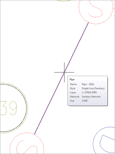
2. Pause your cursor over the pipe. The tooltip will appear indicating the pipe information, including the pay item, as shown in Figure 18-17a.
3. Select the pipe, right-click, and select Swap Part, as shown in Figure 18-17b. This will display the Swap Part Size dialog.
Figure 18-17: Swapping out the part size (right)
4. Select 12 Inch PVC from the list of sizes, and then click OK to dismiss the dialog.
5. Pause near the newly sized pipe and notice that the tooltip no longer shows the pay item, as shown in Figure 18-18.
Figure 18-18: The tooltip after the part has been swapped to a part with no assignment in the parts list
6. Open the QTO Manager palette if it’s not already open.
7. Enter 12-inch pipe in the text box to filter the pay item list.
8. Select the 12-INCH PIPE CULVERT item in the list, right-click, and choose Assign Pay Item from the context menu.
9. Select the pipe you just modified to assign the pay item. The command line should echo Pay item 60201-0400 assigned to object.
10. Press ↵ to end the assignment command.
Next, you will remove an extraneous pay item assignment on the sanitary outfall:
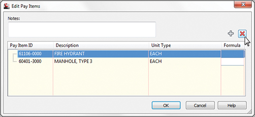
11. Click the Edit Pay Items On Specified Object button in the QTO Manager.
12. Pick the downstream sanitary manhole connected to the pipe you edited in the previous step.
13. Select the FIRE HYDRANT row, and then click the red X in the upper right to remove this pay item from the structure, as shown in Figure 18-19.
Figure 18-19: Editing pay item assignments: deleting an erroneous fire hydrant
14. Click OK to dismiss the dialog.
15. Close the QTO Manager palette.
You might wonder why Civil 3D allows you to have multiple pay items on a single object. Linear feet of striping and tree counts can both be derived from street lengths; bedding and pipe material can both be calculated from pipe objects. You can also add related tasks to an item. For instance, a tree is usually a pay item by itself, but the labor to install the tree may be treated as a separate pay item.
You’ve now built up a list of pay items, tagged your drawing a number of different ways, updated and modified pay item data, and looked at formulas in pay items. In the next section, you’ll make a final check of your assignments before running reports.
Highlighting Pay Items
Before you run any reports, it’s a good idea to make a cursory pass through your drawing and look at what items have had pay items assigned and what items have not. This review will allow you to hopefully catch missing items (such as hydrants added after the pay item assignment was done), as well as see any items that perhaps were blocked in with unnecessary pay items already assigned. In this exercise, you’ll look at tools for highlighting objects with and without pay item assignments:
1. Open the Highlighting Pay Items.dwg file.
2. From the Analyze tab’s QTO panel, select QTO Manager.
3. In the QTO Manager, select Highlight Objects With Pay Items, as shown in Figure 18-20.
Figure 18-20: Turning on highlighting for items with pay items assigned

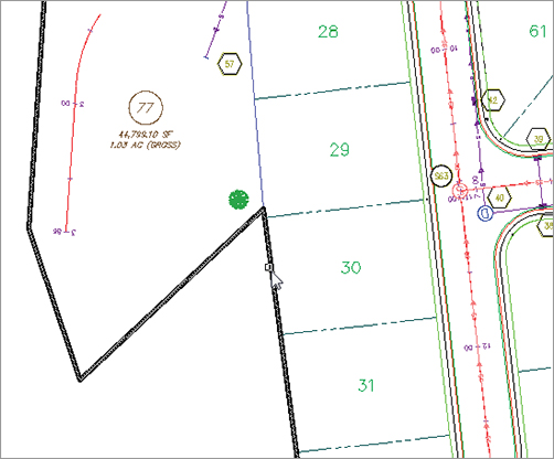
4. Pan to the middle of the drawing and note that some of the lot lines are still bright magenta instead of muted. This means they have a pay item assigned.
5. In the QTO Manager, select Highlight Objects Without Pay Items from the drop-down menu shown in Figure 18-20. Note that most of the alignments and lot lines are now highlighted.
6. In the QTO Manager, select Clear Highlight to return the drawing view to normal.
While objects are highlighted, you can add and remove pay items as well as any other normal AutoCAD work you might perform. This makes it easier to correct any mistakes made during the assignment phase of the process. Finally, be sure to clear highlighting before exiting the drawing, or your peers might wind up awfully confused when they open the file!