
Profile and alignment labels can take on many forms. On an alignment you may want to show labels every 100′ in addition to PC, PT, and PI information. On a profile, you will want tangent grades, curve information, and grade breaks.
For every element you wish to label, a separate style controls the look and behavior of that label.
Label Sets
A label set is a grouping of labels that apply to the same object. In lieu of having one big style that accounts for multiple aspects of an object, the labels are broken out into specific pieces to allow you more control.
Label sets come into play with alignments and design profiles. When you look at an alignment or profile and see labels, you are usually seeing multiple label styles in action.
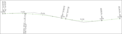
Consider the alignment shown in Figure 19-85. How many labels are there on this alignment? The geometry points, the major ticks, the minor ticks, superelevation stations, and design speed are all separate labels.
Figure 19-85: One alignment, five label styles in play
How did those labels get here? When you first created the alignment or profile, one of the options was to specify a label set (as shown in Figure 19-86a). The labels from the set are applied as a batch to the object.
To edit which labels are applied to an alignment or profile, select Add/Edit Station Labels from the context tab (as shown in Figure 19-86b).
Figure 19-86: Specifying an alignment label set upon creation (a) and accessing the label list after creation (b)
Label sets also dictate the placement of the annotation. An alignment label set controls the major and minor station labeling increment. A profile label set has a big job to do in helping you place labels in the correct location with respect to both the design and the profile view. In Figure 19-87, Dim Anchor Opt and Dim Anchor Val control whether the label is placed on the object or in relation to the graph.
Figure 19-87: Profile labels and placement

Alignment Labels
You’ll create individual label styles over the next couple of exercises and then pull them together with a label set. At the end of this section, you’ll apply your new label set to the alignments.
Major Station
Major station labels typically include a tick mark and a station callout. In this exercise, you’ll build a style to show only the station increment and run it parallel to the alignment:
1. Open the Alignment Labels.dwg file.
2. Switch to the Settings tab, and expand the Alignment Label Styles Station Major Station branch.
3. Right-click the Parallel With Tick style and select Copy. The Label Style Composer dialog appears.
4. On the Information tab, type Station Index Only in the Name field.
5. Switch to the Layout tab.
6. Click in the Contents Value field, under the Text property, and then click the ellipsis button to open the Text Component Editor dialog.
7. Click in the preview area, and delete the text that’s already there.
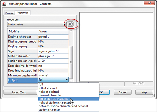
8. Click in the Output Value field, and click the down arrow to open the drop-down list.
9. Select the Left Of Station Character option, as shown in Figure 19-88 (you may have to scroll down). Click the insert arrow circled in the figure.
Figure 19-88: Modifying the Station Value Output value in the Text Component Editor dialog
10. Click OK to close the Text Component Editor dialog.
11. Click OK to close the Label Style Composer dialog.
The label style now shows in your label styles, but it’s not applied to any alignments yet.
Geometry Points
Geometry points reflect the PC, PT, and other points along the alignment that define the geometric properties. The existing label style doesn’t reflect a plan-readable format, so you’ll copy it and make a minor change in this exercise:
1. Continue working in the Alignment Labels.dwg file.
2. Expand the Alignment Label Styles Station Geometry Point branch.
3. Right-click the Perpendicular With Tick And Line style, and select Copy to open the Label Style Composer dialog.
4. On the Information tab, change the name to Perpendicular with Line.
5. Switch to the General tab.
6. Change the Readability Bias setting to 90. This value will force the labels to flip at a much earlier point.
7. Switch to the Layout tab and make these changes:
- Set the Component Name field to the Tick option.
- Click the Delete Component button (the red X button).
- Click the Create New Line Component button.
- Change the line angle to 90.
- Change the component to Geometry Point & Station. Change the Anchor Component to Line.1. Change the Anchor Point to End. Change Rotation Angle to 0.
- Click OK.
8. Click OK to close the Label Style Composer dialog. Save the drawing.
This new style flips the plan-readable labels sooner and includes a line with the label.
Alignment Label Set
Once you have several labels you wish to use on an alignment, it is time to save them as an alignment label set. Continue working in the Alignment Labels.dwg file.
1. Expand the Alignment Label Styles Label Sets branch.
2. Right-click Label Sets, and select New to open the Alignment Label Set dialog.
3. On the Information tab, change the name to Paving.
4. Switch to the Labels tab.
5. Set the Type field to the Major Stations option and the Major Station Label Style field to the Station Index Only style that you just created; then click the Add button.
6. Set the Type field to the Minor Stations option and the Minor Station Label Style field to the Tick option; then click the Add button.
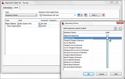
7. Set the Type field to Geometry Points and the Geometry Point Label Style field to Perpendicular With Line. Then click the Add button to open the Geometry Points dialog, as shown Figure 19-89. Deselect the Alignment Beginning and Alignment End options as shown. Click OK to dismiss the dialog.
Figure 19-89: Deselecting the Alignment Beginning and Alignment End Geometry Point options
8. Three label types will now be shown in the Alignment Label Set dialog. Click OK to dismiss this dialog.
In the next exercise, you’ll apply your label set to the example alignment and then see how an individual label can be changed from the set. Continue working in the Alignment Labels.dwg file.
1. Select the Example alignment on screen.
2. Right-click, and select Edit Alignment Labels to display the Alignment Labels dialog. This dialog shows which labels are currently applied to the alignment. Initially, it will be empty.
3. Click the Import Label Set button near the bottom of this dialog.
4. In the Select Style Set drop-down list, select the Paving Label Set and click OK. The alignment labels list populates with the option you selected.
5. Click OK to dismiss the dialog.
6. When you’ve finished, zoom in on any of the major station labels.
7. Hold down the Ctrl key, and select the label. Notice that a single label is selected, not the label set group.
8. Right-click and select Label Properties.
9. The Label Properties dialog appears, allowing you to pick another label style from the drop-down list.
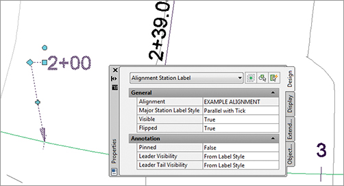
10. Change the Label Style value to Parallel With Tick, and change the Flip Label value to True, as shown in Figure 19-90.
Figure 19-90: Modifying a single label’s properties through base AutoCAD properties
11. Press Esc to deselect the label item.
If you add labels to an alignment and like the look of the set, use the Save Label Set option. By using alignment label sets, you’ll find it easy to standardize the appearance of labeling and stationing across alignments. Building label sets can take some time, but it’s one of the easy, effective ways to enforce standards.
Station Offset Labeling
Beyond labeling an alignment’s basic stationing and geometry points, you may want to label points of interest in reference to the alignment. Station offset labeling is designed to do just that. In addition to labeling the alignment’s properties, you can include references to other object types in your station-offset labels. The objects available for referencing are as follows:
- Other alignments
- COGO points
- Parcels
- Profiles
- Surfaces
In Chapter 10, you used special alignment labels that referenced other alignments to make adjusting your design easier. In this exercise, you will make a similar type of label. The label you create in the following exercise finds the intersection of two alignments.
1. Open the Advanced Alignment Labels.dwg drawing file.
2. On the Settings tab, expand Alignment Label Styles Station Offset.
3. Right-click Station And Offset, and select Copy to open the Label Style Composer dialog.
4. On the Information tab, change the name of your new style to Alignment Intersection.
5. Switch to the Layout tab. In the Component Name field, delete the Marker component.
6. In the Component Name field, select the Station Offset component.
7. Change the name to Main Alignment.
8. In the Contents Value field, click the ellipsis button to bring up the Text Component Editor.
9. Select the text in the preview area and delete it all.
10. Type Sta. in the preview area; be sure to leave a space after the period.
11. In the Properties drop-down field, select Station Value. Set the Precision to 0.01.
12. Click the insert arrow in the Text Component Editor dialog; press the right arrow on your keyboard to move your cursor to the end of the line, and type one space.
13. In the Properties drop-down field, select Alignment Name.
14. Click the insert arrow to add this bit of code to the preview.
15. Click your mouse in the preview area, or press the right arrow or End key. Move to the end of the line, and type an equal sign (=). Your Text Component Editor should look like Figure 19-91.
Figure 19-91: The start of the alignment label style

16. Click OK to return to the Label Style Composer dialog.
17. Under the Border Property, set the Visibility field to False.
18. Select Reference Text from the drop-down list next to the Add Component tool.
19. In the Select Type dialog that appears, select Alignment and click OK.
20. Change the name to Intersecting Alignment.
21. In the Anchor Component field, select Main Alignment.
22. In the Anchor Point field, select Bottom Left.
23. In the Attachment field, select Top Left. When you choose the anchor point and attachment point in this fashion, the bottom left of the Main Alignment text is linked to the top left of the Intersection Alignment text.
24. Click in the Contents field, and click the ellipsis button to open the Text Component Editor.
25. Delete the generic label text that currently appears in the preview area.
26. Type Sta. in the preview area; be sure to leave a space after the period.
27. In the Properties drop-down list, select Station Value.
28. Click the insert arrow in the Text Component Editor dialog, and then move your cursor using the right arrow on your keyboard or End key, and add a space.
29. In the Properties drop-down list, select Alignment Name.
30. Click the insert arrow to add this bit of code to the preview.
31. Click OK to exit the Text Component Editor, and click OK again to exit the Label Style Composer dialog.
32. Add the label to the drawing by selecting the Annotate tab and clicking Add Labels. Change the label settings to match those shown in Figure 19-92 and click Add. Watch the command line for placement instructions. You will be prompted to select the main alignment, intersection point, and offset. You will then be prompted to click the intersecting alignment.
Figure 19-92: Adding the new alignment label

33. Click the label to select it and reveal the grips. Select the square grip and drag it away from the current location to form a leader.
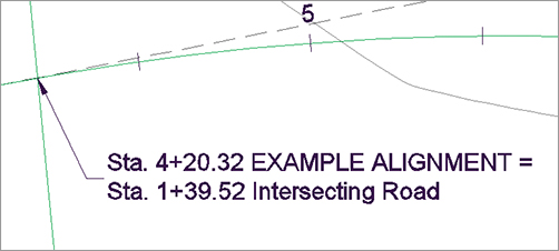
Your completed label should look like Figure 19-93.
Figure 19-93: The completed alignment label with reference text
Profile Labels
It’s important to remember that the profile and the profile view aren’t the same thing. The labels discussed in this section are those that relate directly to the profile. This usually means station-based labels, individual tangent and curve labels, or grade breaks. You’ll look at individual label styles for these components and then at the concept of the label set.
Profile Label Sets
As with alignments, you apply labels as a group of objects separate from the profile in the form of profile label sets. In this exercise, you’ll learn how to add labels along a profile object:
1. Open the Profile Labels.dwg file.
2. Pick the blue layout profile (the profile with two vertical curves) to activate the profile object.

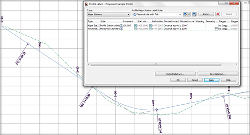
3. Select Edit Profile Labels from the Labels panel to display the Profile Labels dialog (see Figure 19-94).
Figure 19-94: An empty Profile Labels dialog
Selecting the type of label from the Type drop-down menu changes the Style drop-down menu to include styles that are available for that label type. Next to the Style drop-down menu are the usual Style Edit/Copy button and a preview button. Once you’ve selected a style from the Style drop-down menu, clicking the Add button places it on the profile. The middle portion of this dialog displays information about the labels that are being applied to the profile selected; you’ll look at that in a moment.
4. Choose the Major Stations option from the Type drop-down menu. The name of the second drop-down menu changes to Profile Major Station Label Style to reflect this option. Set the style to Profile Station Labels in this menu.
5. Click Add to apply this label to the profile.
6. Choose Horizontal Geometry Points from the Type drop-down menu.
7. The name of the Style drop-down menu changes to Profile Horizontal Geometry Point. Select the Horizontal Geometry Station style, and click Add again to display the Geometry Points dialog shown in Figure 19-95. This dialog lets you apply different label styles to different geometry points if necessary.
Figure 19-95: The Geometry Points dialog appears when you apply labels to horizontal geometry points.
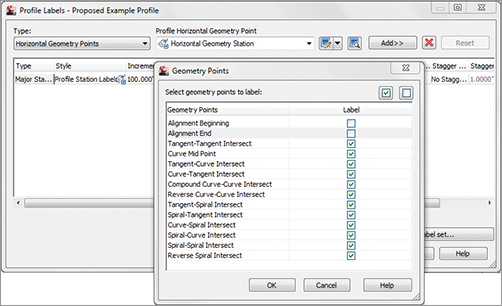
8. Deselect the Alignment Beginning and Alignment End rows, as shown in Figure 19-95, and click OK to close the dialog.
9. Click the Apply button. Drag the dialog out of the way to view the changes to the profile (see Figure 19-96).
Figure 19-96: Labels applied to major stations and alignment geometry points
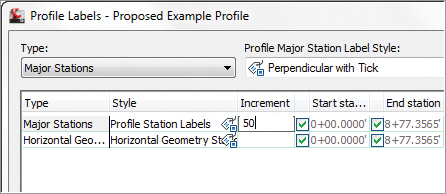
10. In the middle of the Profile Labels dialog, change the Increment value in the Major Stations row to 50, as shown in Figure 19-97. This modifies the labeling increment only, not the grid or other values.
Figure 19-97: Modifying the major station labeling Increment
11. Click OK to close the Profile Labels dialog.
As you can see, applying labels one at a time could turn into a tedious task. After you learn about the types of labels available, you’ll revisit this dialog and look at the two buttons at the bottom for dealing with label sets.
Line Labels
Line labels in profiles are typically used to convey the slope or length of a tangent segment. In this exercise, you’ll add a length and slope to the layout profile:
1. Continue working in the Profile Labels.dwg file.
2. Switch to the Settings tab of Toolspace.
3. Expand the Profile Label Styles Line branches.
4. Right-click Percent Grade, and select the New option to open the Label Style Composer dialog and create a child style.
5. On the Information tab, change the name to Length and Percent Grade.
6. Switch to the Layout tab and make these changes:
- Change Attachment to Top Center.
- Set the Y-offset to –0.025.
- Set Background Mask to True.
7. Click in the cell for the Contents value, and click the ellipsis button to display the Text Component Editor.
8. Change the Properties drop-down menu to the Tangent Slope Length option and the Precision value to 0.01, as shown in Figure 19-98.
Figure 19-98: The Text Component Editor with the values for the Tangent Slope Length entered
9. Click the insert arrow, and then add a foot symbol, a space, an @ symbol, and another space in the editor’s preview pane so that it looks like Figure 19-98.
10. Click OK to close the Text Component Editor, and click OK again to close the Label Style Composer dialog.
11. Pick the layout profile and select Edit Profile Labels from the Labels panel to display the Profile Labels dialog.
12. Change the Type field to the Lines option. The name of the Style drop-down menu changes to Profile Tangent Label Style. Select the Length And Percent Grade option.
13. Click the Add button, and then click OK to exit the dialog. The profile view should look like Figure 19-99.
Figure 19-99: A new line label applied to the layout profile

Where Is That Distance Being Measured?
The tangent slope length is the distance along the horizontal geometry between vertical curves. This value doesn’t include the tangent extensions. There are a number of ways to label this length; be sure to look in the Text Component Editor if you want a different measurement.
Curve Labels
Vertical curve labels are one of the most confusing aspects of profile labeling. Many people become overwhelmed rapidly because there’s so much that can be labeled and there are so many ways to get all the right information in the right place. In this quick exercise, you’ll look at some of the special label anchor points that are unique to curve labels and how they can be helpful:
1. Open the Curve Profile Labels.dwg file.
2. Pick the layout profile and select Edit Profile Labels from the Labels panel to display the Profile Labels dialog.
3. Choose the Crest Curves option from the Type drop-down menu. The name of the Style drop-down menu changes. Select the Crest Only option.
4. Click the Add button to apply the label.
5. Choose the Sag Curves option from the Type drop-down menu. The name of the Style drop-down menu changes to Profile Sag Curve Label Style. Select and add the Sag Only label style.
6. Click OK to close the dialog; your profile should look like Figure 19-100.
Figure 19-100: Curve labels applied with default Dim Anchor values

Most labels are applied directly on top of the object being referenced. Because typical curve labels contain a large amount of information, putting the label right on the object can yield undesired results. In the following exercise, you’ll modify the label settings to review the options available for curve labels:
1. Continue working in the Curve Profile Labels.dwg file.
2. Pick the layout profile and select Edit Profile Labels from the Labels panel to display the Profile Labels dialog.
3. Scroll to the right, and change both Dim Anchor Opt values for the Crest and Sag Curves to Graph View Top.
4. Change the Dim Anchor Val for both curves to –2.25″, and click OK to close the dialog. Your drawing should look like Figure 19-101.
Figure 19-101: Curve labels anchored to the top of the graph
The labels can also be grip-modified to move higher or lower as needed. By using the top or bottom of the graph as the anchor point, you can apply consistent and easy labeling to the curve, regardless of the curve location or size.
Those Crazy Curve Labels!
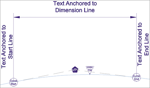
A profile curve label can be as intricate or simple as you desire. Civil 3D gives you many options for where along the curve feature you want your label component to appear. The following illustration shows where some of the commonly used curve locations are in a label.
Grade Breaks
The last label style typically involved in a profile is a grade-break label at PVI points that don’t fall inside a vertical curve, such as the beginning or end of the layout profile. Additional uses include things like water-level profiling, where vertical curves aren’t part of the profile information or existing surface labeling. In this exercise, you’ll add a grade-break label and look at another option for controlling how often labels are applied to profile data:
1. Open the Grade Break Labels.dwg file.
2. Pick the green surface profile (the irregular profile), and then select Edit Profile Labels from the Labels panel to display the Profile Labels dialog.
3. Choose Grade Breaks from the Type drop-down menu. The name of the Style drop-down menu changes. Select the Station Over Elevation style and click the Add button.
4. Click Apply, and drag the dialog out of the way to review the change.
A sampled surface profile has grade breaks every time the alignment crosses a surface TIN line. Why wasn’t your view coated with labels?
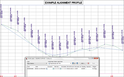
5. Scroll to the right, and change the Weeding value to 50′. Click Apply. The profile labels should appear as shown in Figure 19-102.
Figure 19-102: Grade-break labels on a sampled surface
6. Click OK to dismiss the dialog.
Weeding lets you control how frequently grade-break labels are applied. This makes it possible to label dense profiles, such as a surface sampling, without being overwhelmed or cluttering the view beyond usefulness.
As you’ve seen, there are many ways to apply labeling to profiles, and applying these labels to each profile individually could be tedious. In the next section, you’ll build a label set to make this process more efficient.
Profile Label Sets
Applying labels to both crest and sag curves, tangents, grade breaks, and geometry with the label style selection and various options can be monotonous. Thankfully, Civil 3D gives you the ability to use label sets, as in alignments, to make the process quick and easy. In this exercise, you’ll apply a label set, make a few changes, and export a new label set that can be shared with team members or imported to the Civil 3D template. Follow these steps:
1. Open the Profile Label Sets.dwg file.
2. Pick the layout profile, and then select Edit Profile Labels from the Labels panel to display the Profile Labels dialog.
3. Click the Import Label Set button near the bottom of the dialog to display the Select Style Set dialog.
4. Select the Complete Label Set option from the drop-down menu, and click OK.
5. Click OK again to close the Profile Labels dialog and see the profile view. The label set you chose contains curve labels, grade-break labels, and line labels.
6. Pick the layout profile and select Edit Profile Labels from the Labels panel to display the Profile Labels dialog.
7. Click Import Label Set to display the Select Style Set dialog.
8. Select the _No Labels option from the drop-down menu, and click OK. All the labels from the listing will be removed.
In the next steps, you will add labels to the listing and save the listing as its own label set for future use.
9. Set the active type to Lines. Set Profile Tangent Label Style to Length & Percent Grade. Click Add.
10. Set the active type to Grade Breaks. Set Profile Grade Break Label Style to Station Over elevation. Click Add.
11. Set the type to Crest Curves. Set Profile Crest Curve Label Style to Crest Only. Click Add.
12. Set the type to Sag Curves. Set Profile Sag Curve Label Style to Sag Only. Click Add.
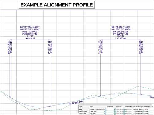
13. Set the Crest Curve and Sag Curve label types to use the Graph View Top as the Dim Anchor Opt. Set both Dim Anchor Val fields to –1.5″, as shown in Figure 19-103.
Figure 19-103: Four label types and dimension anchor settings in the label set to be saved

14. Click the Save Label Set button to open the Profile Label Set dialog and create a new profile label set.
15. On the Information tab, change the name to Road Profile Labels. Click OK to close the Profile Label Set dialog.
16. Click OK to close the Profile Labels dialog.
17. On the Settings tab of Toolspace, select Profile Label Styles Label Sets. Note that the Road Profile Labels set is now available for sharing or importing to other profile label dialogs.
Label sets are the best way to apply profile labeling uniformly. When you’re working with a well-developed set of styles and label sets, it’s quick and easy to go from sketched profile layout to plan-ready output.