
Data shortcuts allow the cross-referencing of design data between drawings. To this end, the data is what is made available, and it’s important to note that the appearance can be entirely different between the host and any number of data shortcuts. We’ll use the term data shortcut or, more simply, shortcut when we discuss selecting, modifying, or updating these links between files.
There are two primary situations in which you need data or information across drawings, and they are addressed with external references (XRefs) or shortcuts. These two options are similar but not the same. Let’s compare:
XRef Functionality An XRef is used when the goal is to get a picture of the information in question. XRefs can be changed by using the layer control, XRef clips, and other drawing-element controls. Though they can be used for labeling across files in Civil 3D 2012, the fact that you have to bring in the entire file to label one component is a disadvantage.
Shortcut Functionality A shortcut brings over the design information but generally ignores the display. Shortcuts only work with Civil 3D objects, so they will have their own styles applied. This may seem like duplicitous work because you have already assigned styles and labels in one drawing and have to do it again, but this functionality offers an advantage in that you can have completely different views of the same data in different drawings.
As noted, only Civil 3D objects can be used with shortcuts, and even then some objects are not available through shortcuts. The following objects are available for use through data shortcuts:
- Alignments
- Surfaces
- Profile data
- Pipe networks
- View frame groups
You might expect that corridor, parcel, assembly, point, or point group information would be available through the shortcut mechanism, but they are not. Parcels and corridors can only be accessed via XRef, but once they’ve been Xreffed, you can use the normal labeling techniques and styles. Now that you’ve looked at what objects you can tackle with shortcuts, you’ll learn how to create them in the next section.
A Note about the Exercises in This Chapter
Many of the exercises in this chapter assume you’ve stepped through the full chapter. It’s difficult to simulate the large number of variables that come into play in a live environment. To that end, many of these exercises build on the previous one. For the easiest workflow, don’t close any files until the end of the chapter.
Additionally, you’ll have to make some saves to data files throughout this chapter. Remember that you can always get the original file from the chapter folder that you downloaded from www.sybex.com/go/masteringcivil3d2012.
Publishing Data Shortcut Files
Shortcut files are XML files that contain pointers back to the drawing containing the object in question. These shortcuts are managed through Prospector and are stored in a working folder. Creating shortcuts is a matter of setting a working folder, creating a shortcut folder within that folder, and then creating the shortcut files. We’ll look at all three steps in this section.
As a precursor to making your first project, you should establish a typical folder structure. Civil 3D includes a mechanism for copying a typical project folder structure into each new project. Once you create a blank copy of the folder structure you’d like to have in place for your projects, you can use it as a starting point when creating a new project within Civil 3D.
1. Open Windows Explorer and navigate to C:Civil 3D Project Templates.
2. Create a new folder titled Mastering.
3. Inside Mastering, create folders called Survey, Engineering, Architecture, and Word, as shown in Figure 17-1.
Figure 17-1: Creating a project template
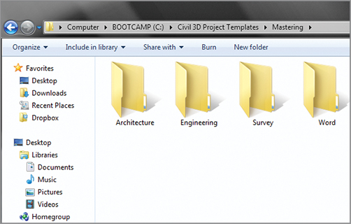
This structure will appear inside Civil 3D and in the working folder when a project is created. We’ve included a Word folder as an example of other, non–Civil 3D–related folders you might have in your project setup for users outside the CAD team, such as accountants or the project manager. If you have any files in these folders (such as a project checklist spreadsheet, a blank contract, or images), they will be checked into new projects as they are created.
The Working and Data Shortcuts Folders
You can think of the working folder as a project directory. The working folder will contain a number of projects, each with a shortcuts folder where the shortcut files reside. Each time you create a new shortcut folder within Prospector, you’ll have the opportunity to create a full project structure. In this exercise, you’ll set the working folder and create a new project:
1. Create a new blank drawing using any template.
2. Within Prospector, make sure the View drop-down list is set to Master View.
3. Right-click the Data Shortcuts branch and select Set Working Folder to display the Browse For Folder dialog shown in Figure 17-2.
Figure 17-2: Creating a new working folder

4. Click Local Disk (C:) to highlight it, and then click the Make New Folder button.
5. Type Mastering Shortcuts as the folder name and click OK to dismiss the dialog.
6. Right-click the Data Shortcuts branch in Prospector, and select New Data Shortcuts Project Folder to display the New Data Shortcut Folder dialog shown in Figure 17-3.
Figure 17-3: Creating a new shortcut folder (aka a project)
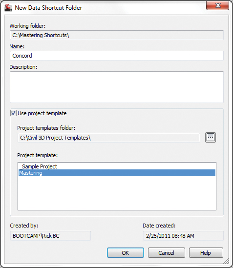
7. Type Concord for the folder name, and toggle on the Use Project Template option, as shown in Figure 17-3.
8. Select the Mastering folder from the list, and click OK to dismiss the dialog. Congratulations, you’ve made a new Civil 3D project! Notice that the Data Shortcuts branch in Prospector now reflects the path of the Concord project.
If you open Windows Explorer and navigate to C:Mastering ShortcutsConcord, you’ll see the folder from the Mastering project template plus a special folder named _Shortcuts, as shown in Figure 17-4. One common issue that arises is that you may already have a project folder inside the working folder. This typically happens during some bidding or marketing work, or during contract preparation. If you already have a project folder established, it will not show up in Civil 3D unless there is a _Shortcuts folder inside it. To this end, you can manually create this folder. There’s nothing special about it—it only has to exist.
Figure 17-4: Your new project shown in Windows Explorer

The working folder and data shortcuts folder are Civil 3D terms for a projects folder and individual projects. If you’re familiar with Land Desktop, the working folder is similar to the project path, with various projects. When you publish or consume data from a project, that drawing will then be associated with the project being used, and from then on, your working folder will change to that project automatically.
Another Way to Look at It
One other option when setting up projects in Civil 3D with shortcuts is to set the working folder path to your particular project folder. Then you could have a CAD folder and within that would be the _Shortcuts folder, which would be the same for every project. This results in a folder structure like H:ProjectsProject NameCAD\_Shortcuts, but some users may find this more useful and easier to manage, particularly if your company standards dictate that the top level of a project folder shouldn’t include something like a _Shortcuts folder. Both methods are workable solutions—just decide on one and stick to it! We’ll use the more conventional approach shown in the previous exercise throughout this text.
Creating Data Shortcuts
With a shortcut folder in place, it’s time to use it. It’s a best practice to keep the drawing files in the same location as your shortcut files, just to make things easier to manage. In this exercise, you’ll publish data shortcuts for the alignments and layout profiles in your project:
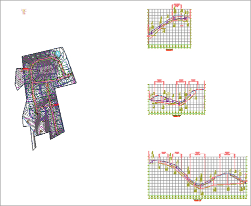
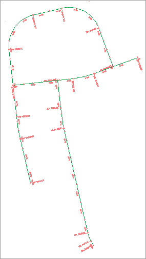
1. Open the CreatingShortcuts.dwg file, which you can download from www.sybex.com/go/masteringcivil3d2012. This drawing contains samples of each shortcut-ready object, as shown in Figure 17-5.
Figure 17-5: The Creating Shortcuts drawing file
2. In Prospector, right-click the Data Shortcuts branch, and select Create Data Shortcuts to display the Create Data Shortcuts dialog shown in Figure 17-6.
Figure 17-6: The Create Data Shortcuts dialog
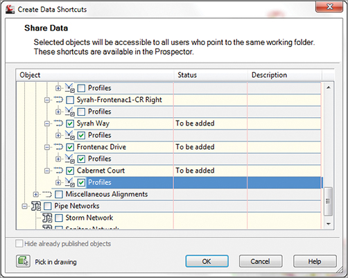
3. Check the EG Surface under the Surface option. Drill down through the Alignments options and check the three major alignments (Syrah Way, Cabernet Court, and Frontenac Drive). Notice that all the subitems will be selected. Leave the pipe networks and view frame groups unchecked. Note that the profiles associated with each alignment are also being selected for publishing.
4. Click OK to dismiss the dialog and create the data shortcuts.
5. Expand the branches under the Data Shortcuts heading as shown in Figure 17-7, and you should see all of the relevant data listed. The listing here indicates that the object is ready to be referenced in another drawing file.
Figure 17-7: Data shortcuts listed in Prospector

In Civil 3D 2008, you had to manually manage the XML data reference files. In Civil 3D 2012, Civil 3D manages these files for you. They are stored in the magic _Shortcuts folder as individual XML files. You can review these XML files using XML Notepad, but it’s worth noting that the first comment in the XML file is PLEASE DO NOT EDIT THIS FILE!. In the past, some users found they needed to edit XML files to fix broken or lost references. This is no longer necessary with the addition of the Data Shortcuts Editor, which we’ll look at later in the section “Updating and Managing References.”
Using Data Shortcuts
Now that you’ve created the shortcut XML files to act as pointers back to the original drawing, you’ll use them in other ways and locations. Once a reference is in place, it’s a simple matter to update the reference and see any changes in the original file reflected in the reference object. In this section, you’ll learn how create and explore these references, as well as update and edit them.
My Screen Doesn’t Look Like That!
Many of the screen captures and paths shown in this chapter reflect the author’s working folders during the creation of the data. Your screen will be different depending on how you have installed the data, network permissions, and so on. Just focus on the content and don’t let the different paths fool you—you’re doing the right steps.
Creating Shortcut References
Shortcut references are made using the Data Shortcuts branch within Prospector. In this exercise, you’ll create references to the objects you previously published to the Concord project:
1. Open the CreatingReferences.dwg file. This is an empty file built on the Extended template.
2. In Prospector, expand Data Shortcuts Centerline Alignments Alignments.
3. Right-click the Cabernet Court alignment and select Create Reference to display the Create Alignment Reference dialog shown in Figure 17-8. Note that the profile data will be created automatically when you create the reference to the Cabernet Court alignment.
Figure 17-8: The Create Alignment Reference dialog

4. Set Alignment Style to Proposed and Alignment Label Set to Major Minor And Geometry Points, as shown in Figure 17-8.
5. Click OK to close the dialog.
6. Perform a zoom extents to find this new alignment.
7. Repeat steps 3 through 5 for the Syrah Way and Frontenac Drive alignments in the shortcuts list. When complete, your screen should look similar to Figure 17-9.
Figure 17-9: Completed alignment references
What’s in a Name?
The name in the XML file doesn’t seem to have much effect on the creation of references; however, it does seem to have an effect on their maintenance. Some users have reported issues with broken references when they changed the name of an object during the Create Reference part of the process. No one has a good feel for why it happens, but we don’t recommend that you test it. Leave the name alone during the create reference step!
Each of these alignments is simply a pointer back to the original file. They can be stylized, stationed, or labeled, but the definition of the alignment cannot be changed. This is more clearly illustrated in a surface, so let’s add a surface reference now:
1. Expand Data Shortcuts Surfaces.
2. Right-click the EG surface and select Create Reference to display the Create Surface Reference dialog.
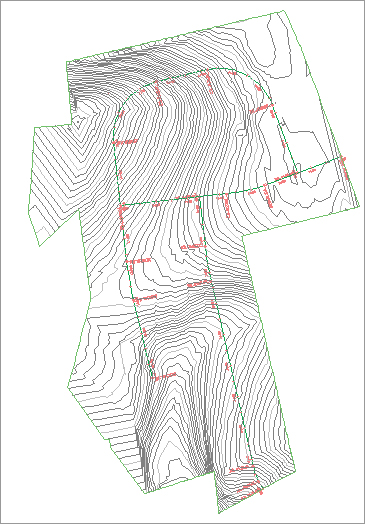
3. Change the Surface Style setting to Contours 1 & 5 Background, and then click OK. Your screen should look like Figure 17-10.
Figure 17-10: Data referenced surface and alignments
4. Expand the Surfaces branch of Prospector and the EG surface, as shown in Figure 17-11.
Figure 17-11: The EG surface in Prospector and the EG Surface Properties dialog

5. Right-click the EG surface and select Surface Properties.
Here are a couple of important things to note:
- The small arrow next to the EG surface name indicates that the surface is a shortcut.
- There’s no Definition branch under the EG surface. Additionally, in the Surface Properties dialog, the entire Definition tab is grayed out, making it impossible to change by using a shortcut.
6. Click OK to close the dialog.
Do I Need to Know This?
Yes, actually you do. Even if you are using Vault as your project-management scheme, there are times and situations where using data shortcuts is the only real solution. Let’s look at a couple of cases where in spite of using Vault, we’ve used data shortcuts to pull the proverbial rabbit out of the hat.
When working with Vault, a drawing is typically attached to a particular project. Though this generally isn’t a problem, it does limit your resources somewhat. When you have a multiphase project that has been divided in Vault, it is impossible to use the Vault mechanism to grab information from a drawing that is not part of the set project.
To get around this limitation, use a shortcut. Open the file containing the desired object and export a shortcut. Then, in the target file, you can import the data shortcut and reference the data accordingly. As the source file changes, the shortcut will update, keeping the two phases in synchronization.
Many firms just starting out with Civil 3D will try to put too much in one drawing. Since the program can handle it, why shouldn’t they? This is fine until they run into a deadline at the end of the project. With no real sharing methodology in place, it becomes almost impossible to split up the work. Also, if you add everything to one drawing and the drawing is suddenly corrupted, then you have lost a lot of work.
Even if you don’t want to get into sharing data at that point in the job, you can use the data shortcut mechanism to break out individual pieces to other files. Once a shortcut has been created in the target file, right-click the object name in Prospector and select Promote, as shown here:
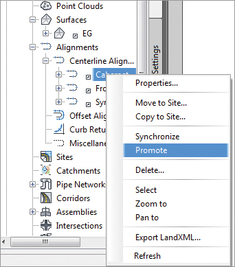
The act of promoting a shortcut breaks the link with the original data and thus isn’t a recommended practice, but sometimes the deadlines win. When it’s time to get the project out the door, you do what works!
To make a reference into a live object in the current drawing, right-click its name and select Promote. This breaks the link to the source information and creates an editable object in the current drawing.
Now that you’ve created a file with a group of references, you can see how changes in the source drawing are reflected in this file.
Updating and Managing References
As it is, if the reference were just a copy of the original data, you’d have done nothing more than cut and paste the object from one drawing to another. The benefit of using shortcuts is the same as with XRefs: when a change is made in the source, it’s reflected in the reference drawing. In this section, you’ll make a few changes and look at the updating process, and then you’ll learn how to add to the data shortcut listings in Prospector.
Updating the Source and Reference
When it’s necessary to make a change, it can sometimes be confusing to remember which file you were in when you originally created a now-referenced object. Thankfully, you can use the tools in the Data Shortcut menu to jump back to that file, make the changes, and refresh the reference:
1. In Prospector, expand Data Shortcuts Alignments Centerline Alignments. Save your drawing.
2. Right-click Cabernet Court and select Open Source Drawing. You can also do this by selecting the object in the drawing window and right-clicking to access the context menu. The Open Source Drawing command appears on the context menu when a reference object is selected.
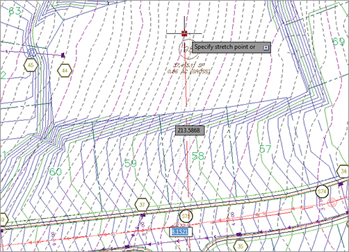
3. Make a grip-edit to Cabernet Court’s northern end, dragging it up and further north, as shown in Figure 17-12.
Figure 17-12: Grip-editing Cabernet Court.
Once a change is made in the source drawing, Civil 3D will synchronize references the next time they are opened. In the current exercise, the reference drawing is already open. The following steps show you how the alert mechanism works in this situation.
4. Press Ctrl+Tab on your keyboard to change to the Creating References.dwg file and make it active, or right-click Creating References.dwg in Prospector and select Switch To. An alert bubble like the one shown in Figure 17-13 appears; it may take a few minutes. You can also choose Creating References Alignments Centerline Alignments in Prospector and you will see a series of warning chevrons.
Figure 17-13: Data Reference Change alert bubble
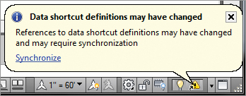
5. Click Synchronize in the alert bubble to bring your drawing current with the design file and dismiss the Panorama window if you’d like. Your drawing will update, and the Cabernet Court alignment will reflect the change in the source. If you do not get the bubble, you can also select individual references within Prospector and right-click them to access the Synchronize command. Or you can right-click on the data shortcut in Prospector and select Synchronize.
This change is simple enough and works well once file relationships are established. But suppose there is a change in the file structure of the source information and you need to make a change. You’ll learn how next.
Managing Changes in the Source Data
Designs change often—there’s no question about that—and using shortcuts to keep all the members of the design team on the same page is a great idea. But in the scenario you’re working with in this chapter, what happens if new, additional alignment data is added to the source file? You’ll explore that in this exercise:
1. Return to CreatingShortcuts.dwg.
2. Thaw the layer called Vino Lane. This is a polyline for a proposed road. It will appear as a thick red polyline.
3. Create a new alignment named Vino Lane. Your screen should look like Figure 17-14.
Figure 17-14: Vino Lane alignment

4. Save the file.
5. In Prospector, right-click Data Shortcuts and select Create Data Shortcuts to display the Create Data Shortcuts dialog.
6. Check the Hide Already Published Objects option in the lower left of the dialog to make finding the new object easier.
7. Check the Vino Lane alignment and click OK to dismiss the dialog.
8. Switch back to the CreatingShortcuts.dwg file, and add the Vino Lane alignment to your data shortcuts as in earlier examples.
9. Save and close the CreatingShortcuts.dwg file.
By using shortcuts to handle and distribute design information, you can keep adding information to the design as it progresses. It’s important to remember that simply saving a file does not create new shortcut files for all of the Civil 3D objects contained within; they have to be created from the Data Shortcuts branch.
Fixing Broken Shortcuts
One of the dangers of linking things together is that eventually you’ll have to deal with broken links. As files get renamed, or moved, the data shortcut files that point back get lost. Thankfully, Civil 3D includes a tool for handling broken links and editing links: the Data Shortcuts Editor. We’ll explore that tool in this exercise. You are going to simulate one of the typical causes of broken shortcuts: that the file was modified.
1. There is a folder on the book’s web page called MovedReference that should be copied to your local data folder (C:Mastering) for this exercise. Explode the Vino Lane alignment so that it is now a polyline.
2. Open the file RepairingReferences.dwg. This file contains a number of references pointing to a file that no longer exists (because it was moved), and Panorama should appear to tell you that five problems were found. Close the Panorama window.
3. In Prospector, select Repairing References ⇒ Surfaces and you will see that EG has a warning chevron next to it.
4. Right-click EG and select Repair Broken References from the context menu to display the Choose The File Containing The Referenced Object dialog.
5. Navigate to the CreatingShortcuts.dwg file in the MovedReference folder. Click Open to dismiss the dialog. An Additional Broken References dialog will appear, as shown in Figure 17-15, offering you the option to repair all the references or cancel.
Figure 17-15: The Additional Broken References dialog
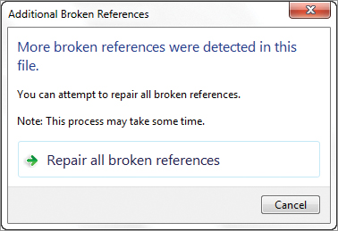
6. Click the Repair All Broken References button to close this dialog. Civil 3D will crawl through the file linked in step 4 and attempt to match the Civil 3D objects with broken references to objects in the selected drawing.
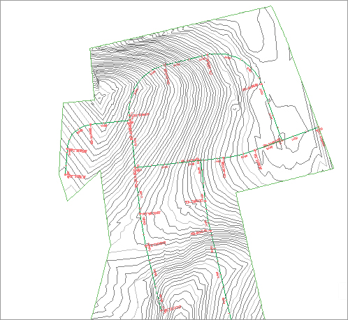
7. Perform a zoom extents, and your drawing should look like Figure 17-16, with a surface and four alignments.
Figure 17-16: Repaired references within an older file
The ability to repair broken links helps make file management a bit easier, but there will be times when you need to completely change the path of a shortcut to point to a new file. To do so, you must use the Data Shortcuts Editor.
The Data Shortcuts Editor
The Data Shortcuts Editor (DSE) is used to update or change the file to which a shortcut points. You may want to do this when an alternative design file is approved, or when you move from preliminary to final design. In the following exercise, you’ll change the Vino Lane alignment shortcut to an alternative design:
1. Make sure RepairingReferences.dwg is still open.
2. In Windows, choose Start All Programs Autodesk Autodesk Civil 3D 2012 Data Shortcuts Editor to load the DSE.
3. Select File Open Data Shortcuts Folder to display the Browse For Folder dialog.
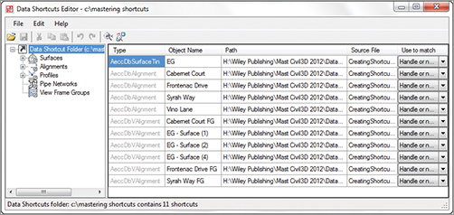
4. Navigate to C:Mastering Shortcuts and click OK to dismiss the dialog. Your DSE should look like Figure 17-17. (Your paths might be different from the author’s.)
Figure 17-17: Editing the Concord data shortcuts
5. On the left, select the Alignments branch to display only the alignments.
6. Click on the Object Name column that presently says Vino Lane, and type New Vino Lane. This is the name of the alignment that we are replacing.
7. Click the Source File column on the New Vino Lane row, type NewVinoLaneAlignment.dwg as the Source filename, and press ↵. Unfortunately, you cannot browse. If you need to change the target file’s path, you will need to change that manually as well.
8. Verify that the last column is set to Handle or Name.
9. Click the Save button in the DSE and switch back to Civil 3D. You should still be in the RepairingReferences drawing file.
10. Expand Data Shortcuts Alignments Centerline Alignments. Right-click Vino Lane and select Repair Broken Shortcut.
11. Scroll up within Prospector, and expand the Alignments branch.
12. Right-click Vino Lane and select Synchronize. The Object Change dialog may open; if so, select Update The Reference Name. You can also dismiss Panorama.
Your screen should look like Figure 17-18, showing a completely different alignment for the Vino Lane alignment.
Figure 17-18: Completed repathing of the Vino Lane shortcut

The ability to modify and repoint the shortcut files to new and improved information during a project without losing style or label settings is invaluable. When you use this function, though, be sure to validate and then synchronize.
What About Vault?
This section focused on the creation and use of data shortcuts. There is another method that is not discussed in this book that uses Vault. Many sources are available for finding out about Vault, such as James Wedding’s Autodesk University presentation “How I Learned to Quit Worrying and Love the Vault,” which can be found at http://au.autodesk.com/?nd=class&session_id=806. Note that to access any AU presentation, you must register. If you are a subscription customer, your registration is your username.