
The general power of Civil 3D lies in its flexibility. The documentation process is tied directly to the objects involved, so making edits to those objects doesn’t create hours of work in updating the documentation. With alignments, there are three major ways to edit the object’s horizontal geometry without modifying the underlying construction:
Graphical Select the object, and use the various grips to move critical points. This method works well for realignment, but precise editing for things like a radius or direction can be difficult without construction elements.
Tabular Use Panorama to view all the alignment segments and their properties; type in values to make changes. This approach works well for modifying lengths or radius values, but setting a tangent perpendicular to a screen element or placing a control point in a specific location is better done graphically.
Segment Use the Alignment Layout Parameters dialog to view the properties of an individual piece of the alignment. This method makes it easy to modify one piece of an alignment that is complicated and that consists of numerous segments, whereas picking the correct field in a Panorama view can be difficult.
In addition to these methods, you can use the Alignment Layout Tools toolbar to make edits that involve removing components or adding to the underlying component count. The following sections look at the three simple edits and then explain how to remove components from and add them to an alignment without redefining it.
Grip-Editing
You already used graphical editing techniques when you created alignments from polylines, but those techniques can also be used with considerably more precision than shown previously. The alignment object has a number of grips that reveal important information about the elements’ creation (see Figure 6-28).
Figure 6-28: Alignment grips
You can use the grips in Figure 6-28 to do the following actions:
- The square grip at the beginning of the alignment, Grip 1, indicates a segment point that can be moved at will. This grip doesn’t attach to any other components.
- The square grip in the middle of the tangents, Grip 2, allows the element to be translated. Other components attempt to hold their respective relationships, but moving the grip to a location that would break the alignment isn’t allowed.
- The triangular grip at the intersection of tangents, Grip 3, indicates a Point of Intersection (PI) relationship. The curve shown is a function of these two tangents and is free to move on the basis of incoming and outgoing tangents, while still holding a radius.
- The triangular grip near the middle of the curve, Grip 4, lets the user modify the radius directly. The tangents must be maintained, so any selection that would break the alignment geometry isn’t allowed.
- Circular grips on the end of the curve, Grip 5, allow the radius of the curve to be indirectly changed by changing the point of the Point of Curvature (PC) of the alignment. You make this change by changing the curve length, which in effect changes the radius.
In the following exercise, you’ll use grip-edits to make one of your alignments match the planner’s intent more closely:
1. Open the EditingAlignments.dwg file.
2. Expand the Alignments branch in Prospector, right-click Frontenac Drive, and select Zoom To.
3. Zoom in on one of the curves in the middle of the alignment. This curve was inserted using the default settings and doesn’t match the guiding polyline well.
4. Select the alignment to activate the grips.
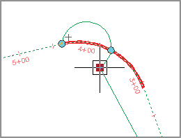
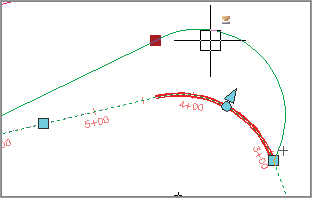
5. Select the triangular grip that appears near the PI, as shown in Figure 6-29, and use your scroll wheel to zoom out.
Figure 6-29: Grip-editing the Frontenac Drive curve

6. Select the circular grip shown in Figure 6-29, and use a Nearest snap to place it on the magenta polyline. Doing so changes the radius without changing the PI.
Your alignment now follows the planned layout. With no knowledge of the curve properties or other driving information, you’ve quickly reproduced the design’s intent.
Tabular Design
When you’re designing on the basis of governing requirements, one of the most important elements is meeting curve radius requirements. It’s easy to work along an alignment in a tabular view, verifying that the design meets the criteria. In this exercise, you’ll verify that your curves are suitable for the design:
1. If necessary, open the EditingAlignments.dwg file.
2. Zoom to the Frontenac Drive alignment, and select it in the drawing window to activate the grips.

3. Select Geometry Editor from the Modify panel. The Alignment Layout Tools toolbar opens.
4. Select the Alignment Grid View tool.
5. Panorama appears, with all the elements of the alignment listed along the left. You can use the scroll bar along the bottom to review the properties of the alignment if necessary. Note that the columns can be resized as well as toggled off by right-clicking the column headers. The segment selected in the alignment grid view is also highlighted in the model, which can also make identifying the segment easier.
Creating and Saving Custom Panorama Views
If you right-click a column heading and select Customize near the bottom of the menu, you’re presented with a Customize Columns dialog. This dialog allows you to set up any number of column views, such as Road Design or Stakeout, that show different columns. These views can be saved, allowing you to switch between views easily. This feature is a great change from previous versions where the column view changes weren’t held or saved between viewings.
6. Notice that you can click in the Radius field to change it. You will learn more about constraints later this chapter.
7. Click the check box to dismiss Panorama, and then close the toolbar.
Panorama allows for quick and easy review of designs and for precise data entry, if required. Grip-editing is commonly used to place the line and curve of an alignment in an approximate working location, but then you use the tabular view in Panorama to make the values more reasonable—for example, to change a radius of 292.56 to 300.00.
Component-Level Editing
Once an alignment gets more complicated, the tabular view in Panorama can be hard to navigate, and deciphering which element is which can be difficult. In this case, reviewing individual elements by picking them on screen can be easier:
1. Continue with the EditingAlignments.dwg file.
2. Zoom to Frontenac Drive, and select it to activate the grips.
3. Select Geometry Editor from the Modify panel. The Alignment Layout Tools toolbar appears.
4. Select the Sub-Entity Editor tool to open the Alignment Layout Parameters dialog.
5. Select the Pick Sub-Entity tool on the Alignment Layout Tools toolbar.
6. Pick the first line on the northeast corner of the site to display its properties in the Alignment Layout Parameters dialog (see Figure 6-30). Since this alignment was created from objects, all line segments are not constrained—that is, they do not hold any relationship between the other segments that make up the alignment.
Figure 6-30: The Alignment Layout Parameters dialogs for the first line (on the left) and the first curve (on the right) on Frontenac Drive
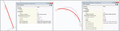
7. Zoom in, and pick the first curve. Notice that the Radius Tangency now reports that it is constrained on both sides (Free).
8. Change the value in the Radius field to 300, and watch the screen update. This value is too far from the original design intent to be a valid alternative.
9. Change the value in the Radius field to 100, and again watch the update. This value is closer to the design and is acceptable.
10. Close the Alignment Layout Parameters dialog and the Alignment Layout Tools toolbar.
By using the Alignment Layout Parameters dialog, you can concisely review all the individual parameters of a component. In each of the editing methods discussed so far, you’ve modified the elements that were already in place. We will look at how to change the makeup of the alignment itself, not just the values driving it. But now, let’s look at some of the constraints and understand how they work.
Understanding Alignment Constraints
In the previous exercise you were exposed to constraints. The various constraints will help keep geometry together to maintain tangency or to maintain the radius.
When an alignment is created from objects, the lines are not constrained (Fixed). This is the same if you select the Draw Two Lines – Fixed from the Alignment Layout Tools toolbar. The curves are all constrained on both sides (Free). When you grip-edit a line or arc, the lines maintain tangency to the arc, but the arc loses its original radius (Figure 6-31).
Figure 6-31: Gripping on an alignment with curves constrained on both sides

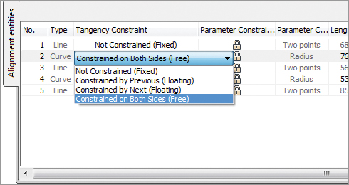
You may have noticed in Panorama the Tangency Constraint field. What you may not have noticed is that you can click on any segment and change constraints (Figure 6-32). You can also change the constraints in the Sub-entity Editor.
Figure 6-32: The tangency constraints in Panorama
1. Select the Frontenac Drive alignment. From the Modify panel, select Geometry Editor.
2. In the Alignment Layout Tools toolbar, select the Alignment Grid View.
3. Click in the Tangency Constraint field for the first curve and change to Not Constrained (Fixed).
4. Now grip-edit the curve and notice how it does not maintain any tangency or radius (Figure 6-33).
Figure 6-33: Gripping on an alignment with curves using Not Constrained
5. Click in the Tangency Constraint field for the first curve and change to Constrained By Previous (Floating).
6. Grip-edit the curve again and notice that the curve maintains its tangency with the previous line, but does not for the following line (Figure 6-34).
Figure 6-34: Gripping on an alignment with curves using Constrained By Previous

7. Click in the Tangency Constraint field for the first curve and change to Constrained By Next (Floating).
8. Grip-edit the curve. See that the curve now maintains its tangency with the following line, but not the previous line (Figure 6-35).
Figure 6-35: Gripping on an alignment with curves using Constrained By Next
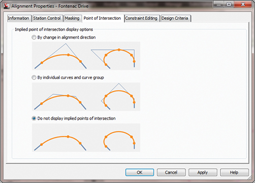
When you click on an alignment that contains curves and select alignment properties, some additional options become available. In the Point Of Intersection tab, you can select whether you want to visually show points of intersection by a change in alignment direction or by individual curves and curve group. The default is to not display any implied points of intersection (Figure 6-36).
Figure 6-36: The Point Of Intersection tab
In the Constraint Editing tab, you can select if you wish to always perform any implied tangency constraint swapping and whether to lock all parameter constraints (Figure 6-37).
Figure 6-37: The Constraint Editing tab

Changing Alignment Components
One of the most common changes is adding a curve where there was none before or changing the makeup of the curves and tangents already in place in an alignment. Other design changes can include swapping out curves for tangents or adding a second curve to smooth a transition area.
Sometimes the Planner Is Right
It turns out that your perfect reverse curve isn’t allowed by the current ordinances for subdivision design! In this example, you’ll go back to the design the planner gave you, and place a tangent between the curves:
1. Open the AlignmentReverseEdit.dwg file.
2. Select the ReverseCurve alignment to activate the grips.
3. Select Geometry Editor from the Modify panel. The Alignment Layout Tools toolbar appears.
4. Select the Delete Sub-Entity tool.
5. Pick the two curves to remove them. Note that the last tangent is still part of the alignment—it just isn’t connected.
6. Select the Free Curve Fillet (Between Two Entities, Through Point) option.
7. Ctrl+click the line on the south, and then using the midpoint osnap, select the midpoint of the very small line that originally connected the two arcs.
8. Repeat the Free Curve Fillet (Between Two Entities, Through Point) option. Select the arc just drawn, and then select the upper line endpoint.
9. Use the Delete Sub-Entity tool to delete the small line. Your reverse curve is complete.

So far in this chapter, you’ve created and modified the horizontal alignments, adjusted them on screen to look like what your planner delivered, and tweaked the design using a number of different methods. Now let’s look beyond the lines and arcs and get into the design properties of the alignment.