
Before you can efficiently work with alignments, you must understand two major concepts: the interaction of alignments and sites, and the idea of geometry that is fixed, floating, or free.
Alignments and Sites
Prior to Civil 3D 2008, alignments were always a part of a site and interacted with the topology contained in that site. This interaction led to the pickle analogy: alignments are like pickles in a mason jar. You don’t put pickles and peppers in the same jar unless you want hot pickles, and you don’t put lots and alignments in the same site unless you want subdivided lots.
Civil 3D now has two ways of handling alignments in terms of sites: They can be contained in a site as before, or they can be independent of a site.
Both the alignments contained in a site and independent of a site can be used to cut profiles or control corridors, but only the alignments contained in a site will react with and create parcels as a member of a site topology.
Unless you have good reason for them to interact (as in the case of an intersection), it makes sense to create alignments outside of any site object. They can be moved later if necessary. For the purpose of the exercises in this chapter, you won’t place any alignments in a site.
Alignment Entities
Civil 3D recognizes four types of alignments: centerline alignments, offset alignments, curb return alignments, and miscellaneous alignments. Each alignment type can consist of three types of entities or segments: lines, arcs, and spirals. These segments control the horizontal alignment of your design. Their relationship to one another is described by the following terminology:
- Fixed segments are fixed in space (see Figure 6-1). They’re defined by connecting points in the coordinate plane and are independent of the segments that occur either before or after them in the alignment. Fixed segments may be created as tangent to other components, but their independence from those objects lets you move them out of tangency during editing operations. This feature can be helpful when you’re trying to match existing field conditions.
Figure 6-1: Alignment fixed segments
- Floating segments float in space but are attached to a point in the plane and to some segment to which they maintain tangency (see Figure 6-2). Floating segments work well in situations where you have a critical point but the other points of the horizontal alignment are flexible.
Figure 6-2: Alignment floating segments

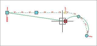
- Free segments are functions of the entities that come before and after them in the alignment structure (see Figure 6-3). Unlike fixed or floating segments, a free segment must have segments that come before and after it. Free segments maintain tangency to the segments that come before and after them and move as required to make that happen. Although some geometry constraints can be put in place, these constraints can be edited and are user dependent.
Figure 6-3: Alignment free segments

During the exercises in this chapter, you’ll use a mix of these entity types to understand them better. Autodesk has also published a drawing called Playground2 that you can find by searching on the Web. This drawing contains examples of most of the types of entities that you can create.