
Using a Feature Line as a Width and Elevation Target
You’ve gained some hands-on experience using alignments and profiles as targets for swale, intersection, and cul-de-sac design. Civil 3D adds options for corridor targets beyond alignments and profiles. You can use grading feature lines, survey figures, or polylines to drive horizontal and/or vertical aspects of your corridor model.
Dynamic Feature Lines Cannot Be Used as Targets
It’s important to note that dynamic feature lines extracted using the Feature Lines From Corridor tool can’t be used as targets. The possibility of circular references would be too difficult for the program to anticipate and resolve.
Imagine using an existing polyline that represents a curb for your lane-widening projects without duplicating it as an alignment, or grabbing a survey figure to assist with modeling an existing road for a rehabilitation project. The next exercise will lead you through an example where a lot-grading feature line is integrated with a corridor model:
1. Open the Feature Line Target.dwg file, which you can download from this book’s web page. This drawing includes a corridor as well as a yellow feature line that runs through a few lots.
2. Zoom to the area of the drawing where the assemblies are located. There is an assembly that includes a LinkWidthAndSlope subassembly attached to the sidewalk on the left side. You’ll be using the yellow feature line as a target for this subassembly.
3. Zoom to the corridor. Select the corridor, and choose Corridor Properties from the contextual Ribbon tab.
4. Switch to the Parameters tab in the Corridor Properties dialog. Click the Set All Targets button. The Target Mapping dialog appears.
5. Click the <None> field next to Target Alignment for the LinkWidthAndSlope subassembly. The Set Width Or Offset Target dialog appears.
6. Choose Feature Lines, Survey Figures And Polylines from the Select Object Type To Target drop-down list (see Figure 10-73).
Figure 10-73: The Select Object Type To Target drop-down list as seen in both the Set Width Or Offset Target and Set Slope Or Elevation Target dialogs
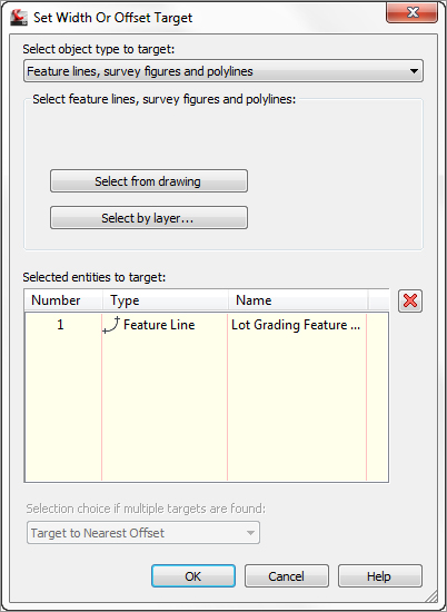
7. Click the Select From Drawing button. When you see the command-line prompt Select feature lines, survey figures or polylines to target:, select the yellow feature line and then press ↵. The Set Width Or Offset Target dialog reappears, with an entry in the Selected Entries To Target area. Click OK to return to the Target Mapping dialog.
If you stopped at this point, the horizontal location of the feature line would guide the LinkWidthAndSlope assembly, and the vertical information would be driven by the slope set in the subassembly properties. Although this has its applications, most of the time you’ll want the feature line elevations to direct the vertical information. The next few steps will teach you how to dynamically apply the vertical information from the feature line to the corridor model.
8. Click the <None> field next to Target Profile for the LinkWidthAndSlope subassembly. The Set Slope Or Elevation Target dialog appears.
9. Make sure Feature Lines, Survey Figures And Polylines is selected in the Select Object Type To Target drop-down.
10. Click the Select From Drawing button. When you see the command-line prompt Select feature lines, survey figures or polylines to target:, select the yellow feature line and then press ↵. The Set Slope Or Elevation Target dialog reappears, with an entry in the Selected Entries To Target area. Click OK to return to the Target Mapping dialog.
11. Click OK to return to the Corridor Properties dialog.
12. Click OK to exit the Corridor Properties dialog. The corridor will rebuild to reflect the new target information and should look similar to Figure 10-74.
Figure 10-74: The corridor now uses the grading feature line as a width and elevation target.

Once you’ve linked the corridor to this feature line, any edits to this feature line will be incorporated into the corridor model. You can establish this feature line at the beginning of the project and then make horizontal edits and elevation changes to perfect your design. The next few steps will lead you through making some changes to this feature line and then rebuilding the corridor to see the adjustments.
13. Select the corridor, right-click, and choose Display Order ⇒ Send To Back. Doing so sends the corridor model behind the target feature line.
14. Switch on your Ortho setting. Use the AutoCAD Move command to move the feature line back approximately 10–20 feet, as shown in Figure 10-75. Note that you could also edit individual vertices or use any of the horizontal feature-line editing tools available in the Grading menu and on the Feature Line toolbar.
Figure 10-75: Move the feature line approximately 10–20 feet deeper into the lot.
15. Select the feature line. Right-click and choose Raise/Lower from the context menu.
16. When you see the command-line prompt Specify elevation difference <1.00>:, type 5 and then press ↵. Each vertex of the feature line rises 5′ vertically. Note that you could also edit individual vertices or use any of the vertical feature-line editing tools available in the Grading menu and on the Feature Line toolbar.
17. Select the corridor. Right-click and choose Rebuild Corridor. The corridor will rebuild to reflect the changes to the target feature line and should look like Figure 10-76.
Figure 10-76: The completed corridor model
Edits to targets—whether they’re feature lines, alignments, profiles, or other Civil 3D objects—drive changes to the corridor model, which in turn drives changes to any corridor surfaces, sections, section views, associated labels, and other objects that are dependent on the corridor model. Brainstorm ways that you can take advantage of this dynamic connection, such as making a corridor surface and then a quick profile or two, so that you can see your iterations of the feature line in immediate action as you work through your design.