
Roundabouts: The Mount Everest of Corridors
If you really understand what went on earlier in this chapter, you are almost ready for roundabout design. You may want to wait to tackle your first roundabout until after reading Chapter 15, “Grading.”
The same concepts apply to a roundabout as for a standard road junction, but you will have several more regions, baselines, and corresponding profiles.
This section will help you prepare files for roundabout design. A roundabout is best done in several corridors:
- Preliminary corridor for circulatory road
- Main corridor with approaches and circulatory road
- Curb island corridors (optional)
Drainage First
Based on your existing ground surface, determine the general direction that you want water to flow away from the center of the roundabout. Use grading tools and a feature line to create the general drainage direction of the roundabout.
Chapter 15 will go into much more depth on creating grading. You will certainly want to have an understanding of grading basics before you tackle a roundabout.
Create a feature line that represents the highest elevations. In the example shown in Figure 10-77, the feature line slopes downward and acts as a ridge to separate water flow. The grading tools are then used to create grading objects and a corresponding surface model called “Roundabout Grading.”
Figure 10-77: Feature lines and grading create a preliminary surface to ensure proper drainage through the roundabout.
The Roundabout Grading surface will be the basis for our profile elevations through the rest of the design process.
Roundabout Alignments
Roundabouts need alignments to guide the design for the same reasons that an intersection needs them. Alignments will be baselines and targets for the approaches and rotary. Create alignments manually with the tools you learned earlier in this chapter, or start with the handy roundabout layout tool.
The roundabout layout tools create horizontal data based on the location of the center of the roundabout and the approach alignments.
In the exercise that follows, you will create the Civil 3D alignments needed to create a roundabout:
1. Open the Roundabout Layout.dwg file, which you can download from this book’s web page.
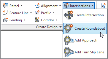
2. From the Home tab, in the Create Design panel, select Intersections Roundabout Create Roundabout, as shown in Figure 10-78.
Figure 10-78: Access the Create Roundabout tool from the Home tab.
3. At the Specify roundabout centerpoint: prompt, use your intersection osnap to select the point where the approaches meet.
4. At the Select approach road: prompt, select all four alignments leading into the roundabout. Press ↵ when you are done.
You now see the Create Roundabout – Circulatory Road screen, shown in Figure 10-79.
Figure 10-79: The first roundabout layout screen for designing the main circulatory road
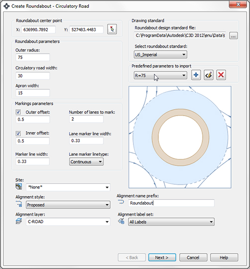
5. From the Predefined Parameters To Import drop-down, choose R=75. This will be the radius from the center of the roundabout to the outermost circular edge of pavement. Set Alignment Layer to C-ROAD and Alignment Label Set to Major And Minor Only. Click Next.
Now, you’ll design the approach road exit and entry geometry. The options in the Create Roundabout – Approach Roads screen (see Figure 10-80) can be set independently for each approach, or you can click Apply To All, which will set the geometry for all four approaches.
Figure 10-80: Approach road widths at entry and exit
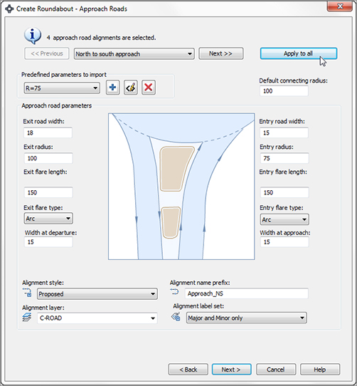
6. Set Predefined Parameters To Import to R=75. For Alignment Label Set, choose Major And Minor Only. Then click the Apply To All button and click Next.
7. In the Create Roundabout – Islands screen (see Figure 10-81), again set Parameters To Import to R=75. Click Apply To All and then click Next.
Figure 10-81: Roundabout Islands parameters

The final screen of the Create Roundabout wizard deals with pavement markings and signage. Notice that you can specify your own blocks for the signs that will be placed in this process.
Everything created in this last step is an AutoCAD polyline or block. The polylines have a global width set to indicate pavement marking thicknesses. These thicknesses are set in the Markings And Signs screen (Figure 10-82).
Figure 10-82: Pavement markings galore!
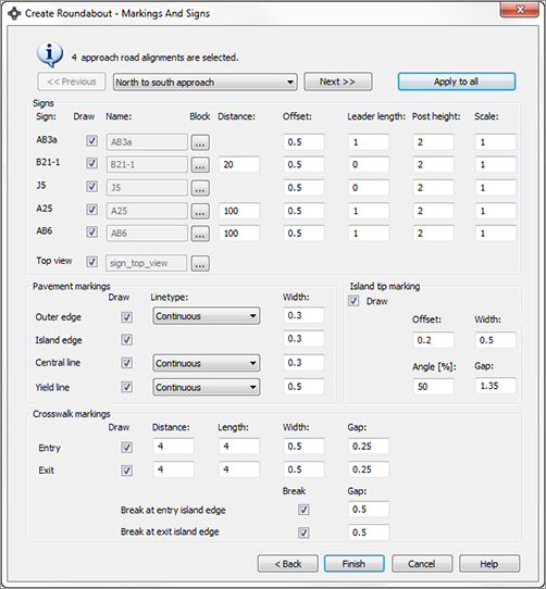
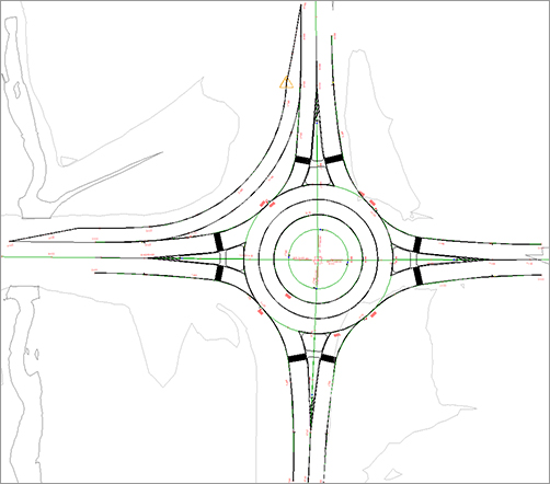
8. Leave all defaults in the Create Roundabout – Markings And Signs screen (Figure 10-82). Click Finish, and your roundabout should resemble Figure 10-83.
Figure 10-83: Completed roundabout alignment layout

Finally, you will add a turn lane in the NW quadrant of the roundabout. When you’re creating slip turn lanes, remember that the turn radius must be large enough to fillet the exit and entry roads without overlapping the other alignments.
When selecting the approach entry and exit alignments, you need to click the shorter approach alignments created by Civil 3D rather than the original approach road. For this reason, the exercise has you select inside the islands, just to be sure.
9. From the Home tab, in the Create Design panel select Intersections Add Turn Slip Lane. When prompted to select the entry approach, select the north approach alignment inside the curb island. When prompted for the exit approach, select the west approach alignment inside the curb island, as shown in Figure 10-84.
Figure 10-84: Entry and exit approach alignments for the slip lane
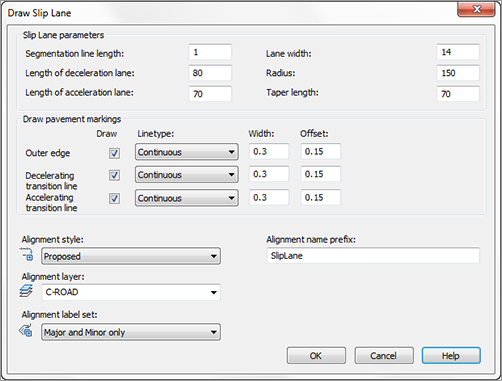
10. In the Draw Slip Lane screen shown in Figure 10-85, set the lane width to 14 and the radius to 150. For the alignment layer, choose C-ROAD and for Alignment Label Set, choose Major And Minor Only. Click OK.
Figure 10-85: Adding a slip lane
Your roundabout will now look like Figure 10-86. The warning symbol is an indicator that the deceleration lane is not tangent to the outer alignment curve, which is normal in this situation.
Figure 10-86: The completed alignment layout with a slip lane
You now have all the alignments you need to start your roundabout design. At this point, you can add geometry to the alignments and modify what Civil 3D has created for you. The pavement markings and signs will only stay dynamic to the roundabout if you modify the initial approaches.
The horizontal layout is complete, but the roundabout design is far from done. No vertical data has been created; that is up to you.
Center Design
All profiles need to meet at the elevations inside the traveled way in the circular pavement area of the roundabout. Therefore, the main circle design comes first.
The example you are seeing has been modified slightly from the default layout created by Civil 3D. The main circular alignment is located at the centerline of the circular portion of the roundabout. You can use any of the circular alignments created by Civil 3D as the basis for this step, as long as your assembly works with the design. Remember to make note of which direction the alignment goes, to ensure the assembly you create is not backwards.
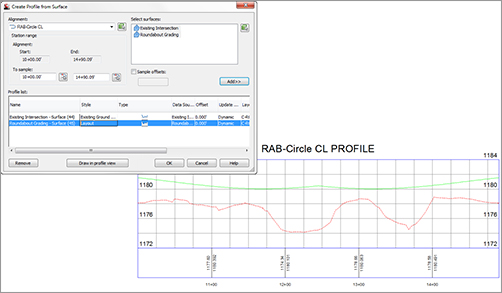
Extract profiles for the main circle design from the Existing Ground and Roundabout Grading surfaces, as shown in Figure 10-87.
Figure 10-87: Extract surface profiles around the main circular alignment.
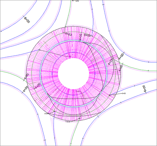
The assembly you create for this preliminary design will also be used in the main design. Decide which alignment will be used as the circular design basis, and create an assembly based on your alignment location and desired geometry, as shown in Figure 10-88.
Figure 10-88: Center assembly for roundabout
When the assembly is complete, you will apply the assembly to the first of several corridors you create. Create a corridor called Preliminary Roundabout Center. Use the main circle alignment (called RAB-Center CL in this example) as the baseline and use the Roundabout Grading profile as the corridor profile. There are no targets or frequencies to set in this corridor.
Create a Top link surface from the Preliminary Roundabout Center. Any approach alignments that touch this surface need to tie into this surface elevation. At this point the roundabout will resemble Figure 10-89.
Figure 10-89: Preliminary center corridor and surface
Profiles for All
You have all the preliminary surfaces in place, and you have all the alignments you need, so it is time to extract profiles from your various surfaces.
Extract surface profiles for all the approach alignments by sampling the existing ground, drainage surface, and preliminary corridor surface.
These profiles will look something like Figure 10-90.
Figure 10-90: Surface profiles needed for design
When you create your design, you will see all your design considerations in the profile views. No matter how you decide to tie into existing ground and slope upward toward the surface, your design needs to tie into the preliminary center surface, as shown in Figure 10-91.
Figure 10-91: Design profiles must tie into the center.

Use techniques you learned earlier in this chapter to assist you. Labels are an especially valuable tool for roundabouts. Keep your profile views organized, as you will have at least three for each approach. If you have a slip turn lane, you will have a profile for that as well.
Tie It All Together
Stretch your legs and go for more coffee. It is time to put this thing together into a completed corridor. When you model the corridor initially, ignore curb islands—you will add them as individual corridors in a later step.
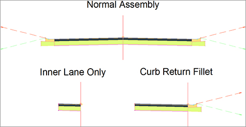
A simple roundabout can be completed using as few as three assemblies. In our example, however, the slip turn lane necessitates a total of four assemblies. In addition to the RAB-Center assembly we examined in Figure 10-88, you will need three more assemblies, as shown in Figure 10-92.
Figure 10-92: Assemblies needed for the main roundabout corridor
These assemblies will be tied to the EOP alignments and profiles as baselines, similar to a traditional intersection. Each quadrant of the roundabout will target at least two alignments and profiles, as shown in Figure 10-93.
Figure 10-93: Roundabout corridor regions and targets
Keep in mind the direction of your alignments. If you build the corridor in stages, check the corridor periodically to make sure it is building correctly.
Create a corridor surface from your completed roundabout lanes. You will likely have to use the Add Interactively tool to add the boundary correctly.
Finishing Touches
The median islands are the last parts to go on the corridor. You can create them using simple grading objects, but since this is a book about mastering skills and this is a chapter about corridors, you should examine the dynamic way.
Create a simple assembly containing the curb and gutter for the curb islands. This will be the assembly that you use with the median corridors (Figure 10-94).
Figure 10-94: Simple assembly containing just the curb and gutter on the median islands
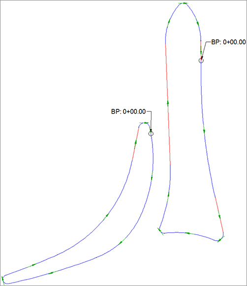
Each median island will need its own alignment. Take note of the direction of the alignments to make sure they are compatible with the curb island assembly. If necessary, change the direction of the alignments using the Reverse Direction tool in the Modify panel of the contextual Ribbon tab. Figure 10-95 shows the bypass island and north island with directions.
Figure 10-95: Several median island alignments with direction shown
The good news is that the elevation data for the medians is already complete. Your main corridor’s surface will act as the profile for each individual median. This also means that once the curb return corridors are created, they will be dynamic to the main corridor. Once these little corridors are created and surface model information has been obtained, you can set them to Rebuild – Automatic and forget all about them.
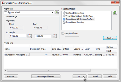
Extract a profile for all the curb return alignments from the Top link surface model from the main roundabout corridor, as shown in Figure 10-96. You do not need to see this profile in a view, so you can click OK to extract.
Figure 10-96: Extract the profile for medians from your main roundabout surface.
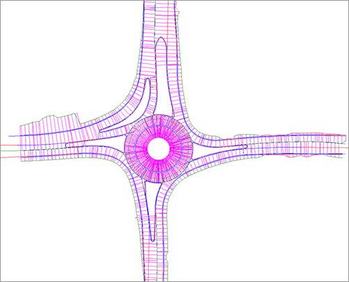
When the design roundabout corridors are complete and surfaces are made, the next step is to merge the surfaces together. Create a final surface model and paste the main roundabout design in first. After the main corridor is pasted in, paste the smaller median corridor surfaces (see Figure 10-97).
Figure 10-97: The completed roundabout
Your next step is to use the corridor fine-tuning techniques you learned earlier in this chapter to ensure your grades are correct and the design is correct. To see an example of a completed corridor using these steps, take a look at Completed Roundabout Corridor example.dwg, which you can download from www.sybex.com/go/masteringcivil3d2012.