
In Chapter 9, you completed a road-widening example with a simple lane transition. Earlier in this chapter, you worked with a roadside-ditch transition, intersections, and cul-de-sacs. These are just a few of the techniques for adjusting your corridor to accommodate a widening, narrowing, interchange, or similar circumstances. There is no single method for building a corridor model; every method discussed so far can be combined in a variety of ways to build a model that reflects your design intent.
Another tool in your corridor-building arsenal is the assembly offset. In Chapter 8, you had your first glimpse of an offset assembly, but in the example that follows you will have a chance to use one for a bike path design.
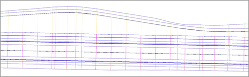
Notice in Figure 10-64 how the frequency lines in the corridor are running perpendicular to the main alignment. The bike path is an alignment that is not a constant offset through the length of the corridor. In this scenario, the cross section of the bike path itself is skewed. This could prove problematic when computing end area volumes for the bike path pavement. This is the result of using an assembly where all of the design is based off one main baseline assembly.
Figure 10-64: A bike bath modeled with a traditional assembly
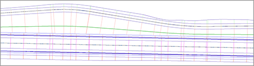
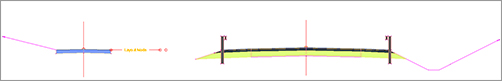
There are several advantages to using an offset assembly instead. The offset assembly requires its own alignment and profile for design. In the corridor that results, a secondary set of frequency lines is generated perpendicular to the offset alignment, as shown in Figure 10-65. Additionally, you can use a marked point assembly to model the ditch between the bike path and the main road.
Figure 10-65: Modeling a bike path with an assembly offset
There are many uses of offset assemblies besides bike paths. Typical examples of when you’ll use an assembly offset include transitioning ditches, widening roads, creating traffic-calming lanes, and introducing interchanges. The assembly in Figure 10-66, for example, includes two assembly offsets. The assembly could be used for transitioning roadside swales, similar to the first exercise in this chapter.
Figure 10-66: An assembly with two offsets representing roadside swale centerlines
Even though each offset requires its own profile, it isn’t always necessary to use Profile Profile Creation Tools from the Create Design panel and design a profile from scratch. Use some creativity to figure out additional methods to achieve your design intent. Extracting a profile from a corridor, sampling a profile from a first-draft surface, importing a profile from another source, copying a main-road profile and moving it to different elevation, and superimposing profiles are all valid methods for creating profiles for targeting and assembly offsets.
In this exercise, you will model a bike path with an assembly offset:
1. Open the Highway 10 with Bike Path_Assembly.dwg file, which you can download from this book’s web page.
2. Zoom to the area of the drawing where the assemblies are located. You’ll see an incomplete assembly called 12′ Lane Road With GR and Bikepath.
3. Click on the main assembly marker. From the contextual Ribbon tab, click Add Assembly Offset in the Modify Assembly panel.
4. At the Specify offset location: prompt, click to the left of the 12′ Lane Road With GR And Bikepath assembly, leaving enough room for the bike lane and ditch. Your result should look like Figure 10-67.
Figure 10-6712: 12′ Lane Road With GR And Bikepath assembly, so far

5. Open the Civil Imperial Subassembly tool palette. Switch to the Basic tab. Select the BasicLane subassembly.
6. In the Advanced Parameters in the Properties dialog box, set Side to Right and Width to 5′. Click to place the subassembly on the offset assembly.
7. Switch the subassembly side to the left and place it on the offset assembly as well. Your assembly should now look like Figure 10-68.
Figure 10-68: 12′ Lane Road With GR And Bikepath assembly with the BasicLane as a bike path

Next you will use a MarkPoint assembly to set the stage for building a ditch between the bike path and the main road.
8. Switch to the Generic tab in the subassemblies tool palette. Click the MarkPoint subassembly.
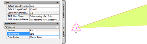
9. Change the Point Name to BIKE (use all capital letters).
10. Click on the outermost point of the left shoulder subassembly. Your marker will look like Figure 10-69.
Figure 10-69: A close-up of the MarkPoint subassembly
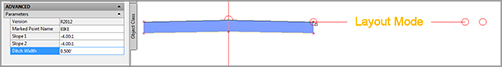
11. From the Subassemblies tool palette, click the LinkSlopesBetweenPoints subassembly. Set Marked Point Name to BIKE (use all capital letters again). Set Ditch Width to 0.5′ and click on the right side of the bike path. The offset assembly will now look like Figure 10-70.
Figure 10-70: The LinkSlopesBetweenPoints subassembly in layout mode
12. Add a LinkSlopeToSurface generic link subassembly. Set the Side to Left and Slope to 25%. Place the subassembly on the left side of the bike path. The completed assembly will look like Figure 10-71.
Figure 10-71: The completed assembly with offset
Next, you will create a corridor using this new assembly:
1. Open the Highway 10 with Bikepath_Corridor.dwg file (which you can download from this book’s web page), or continue working in your drawing from the previous exercise.
2. From the Home tab, select Corridor Create Simple Corridor. Name the corridor Bike Path and click OK.
3. For the baseline alignment, right-click and select USH 10. Click OK.
4. For Profile, right-click and select USH 10 Roadway CL Prof. Click OK.
5. For the assembly, select 12′ Lane Road With GR And Bikepath.
6. The only targets needed are the surface targets. Click the <Click here to set all> link and choose Existing Intersection. Click OK.
7. Dismiss the error that comes up in Panorama—you will rectify that issue in the next step. Pan over to the corridor. Notice that the alignment to the west, which represents the bike path centerline, is currently being ignored by the corridor.
8. Select the corridor and open the Corridor Properties dialog. Switch to the Parameters tab. Notice Offset - (1) is not associated with an alignment.
9. Click the alignment field for Offset - (1), select Bike Path, and click OK. Click the profile field for Offset - (1), select Bike Path FG, and click OK.
10. The Bike Path alignment is slightly shorter than the main USH 10 alignment, which explains why you were getting target errors in Panorama. To correct the corridor errors, set the start station for the Offset - (1) region to 0+25.00. Set the end station to 40+00. Click OK to rebuild the corridor. Your completed corridor will resemble the example back in Figure 10-65.
11. Select the corridor by clicking on one of the frequency lines anywhere near the middle of the alignment. Click Section Editor. You may want to change your annotation scale to 1″=1′ to get an unobstructed view of your masterpiece.
12. You’ll see only your mainline assembly in the Section Editor initially. To see the offset baseline, select the Offset - (1) baseline from the drop-down menu, as shown in Figure 10-72.
Figure 10-72: Inside the corridor Section Editor

The Trouble with Bowties
In your adventures with corridors, chances are pretty good that you’ll create an overlapping link or two. These overlapping links are known affectionately as bowties. A mild example can be seen in the following graphic:

An even more pronounced example can be seen in the following river corridor image:
Bowties are problematic for several reasons. In essence, the corridor model has created two or more points at the same x and y locations with a different z, making it difficult to build surfaces, extract feature lines, create a boundary, and apply code-set styles that render or hatch.
When your corridor surface is created, the TIN has to make some assumptions about crossing breaklines that can lead to strange triangulation and incoherent contours, such as in the following graphic:
When you create a corridor that produces bowties, the corridor won’t behave as expected. Choosing Corridors Utilities to extract polylines or feature lines from overlapping corridor areas yields an entity that is difficult to use for additional grading or manipulation because of extraneous, overlapping, and invalid vertices. If the corridor contains many overlaps, you may have trouble even executing the extraction tools. The same concept applies to extracted alignments, profiles, and COGO points.
If you try to add an automatic or interactive boundary to your corridor surface, either you’ll get an error or the boundary jig will stop following the feature line altogether, making it impossible to create an interactive boundary.
To prevent these problems, the best plan is to try to avoid link overlap. Be sure your baseline, offset, and target alignments don’t have redundant or PI locations that are spaced excessively close.
If you initially build a corridor with simple transitions that produce a lot of overlap, try using an assembly offset and an alignment besides your centerline as a baseline. Another technique is to split your assembly into several smaller assemblies and to use your target assemblies as baselines, similar to using an assembly offset. This method was used to improve the river corridor shown in the previous graphics. The following graphic shows the two assemblies that were created to attach at the top of bank alignments instead of the river centerline:
The resulting corridor is shown in the following graphic:
The TIN connected the points across the flat bottom and modeled the corridor perfectly, as you can see in the following image:
Another method for eliminating bowties is to notice the area where they seem to occur and then adjust the regions. If your daylight links are overlapping, perhaps you can create an assembly that doesn’t include daylighting and create a region to apply that new assembly.
If overlap can’t be avoided in your corridor, don’t panic. If your overlaps are minimal, you should still be able to extract a polyline or feature line—just be sure to weed vertices and clean up the extracted entity before using it for projection grading. You can create a boundary for your corridor surface by drawing a regular polyline around your corridor and adding it as a boundary to the corridor surface under the Surfaces branch in Prospector. The surface-editing tools, such as Swap Edge, Delete Line, and Delete Point, can also prove useful for the final cleanup and contour improvement of your final corridor surface.
As you gain more experience building corridors, you’ll be able to prevent or fix most overlap situations, and you’ll also gain an understanding of when they aren’t having a detrimental effect on the quality of your corridor model and resulting surface.