
Creating Subdivision Lot Parcels Using Precise Sizing Tools
The precise sizing tools allow you to create parcels to your exact specifications. You’ll find these tools most useful when you have your roadways established and understand your lot-depth requirements. These tools provide automatic, semiautomatic, and freeform ways to control frontage, parcel area, and segment direction.
Attached Parcel Segments
Parcel segments created with the precise sizing tools are called attached segments. Attached parcel segments have a start point that is attached to a frontage segment and an endpoint that is defined by the next parcel segment they encounter. Attached segments can be identified by their distinctive diamond-shaped grip at their start point and no grip at their endpoint (see Figure 5-21).
Figure 5-21: An attached parcel segment
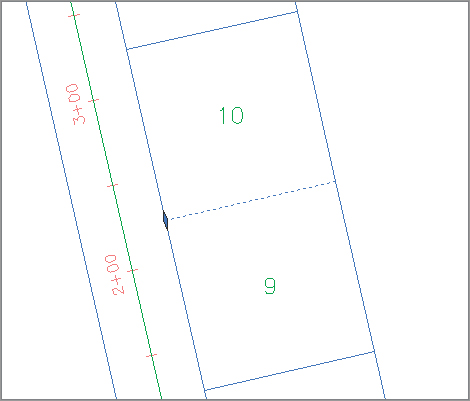
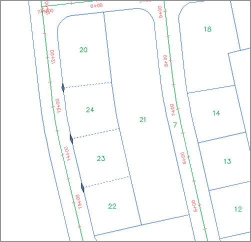
In other words, you establish their start point and their direction, but they seek another parcel segment to establish their endpoint. Figure 5-22 shows a series of attached parcel segments. You can tell the difference between their start and endpoints because the start points have the diamond-shaped grips.
Figure 5-22: A series of attached parcel segments, with their endpoint at the front lot line
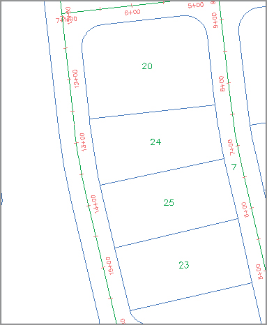
You can drag the diamond-shaped grip along the frontage to a new location, and the parcel segment will maintain its angle from the frontage. If the rear lot line is moved or erased, the attached parcel segments find a new endpoint (see Figure 5-23) at the next available parcel segment.
Figure 5-23: The endpoints of attached parcel segments extend to the next available parcel segment if the initial parcel segment is erased.
Precise Sizing Settings
The precise sizing tools consist of the Slide Angle, Slide Direction, and Swing Line tools (see Figure 5-24).
Figure 5-24: The precise sizing tools on the Parcel Layout Tools toolbar
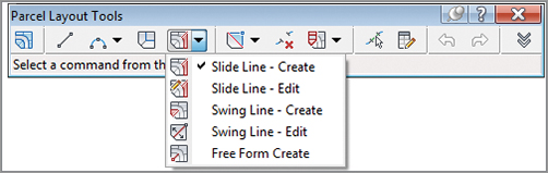
The Parcel Layout Tools toolbar can be expanded so that you can establish settings for each of the precise sizing tools (see Figure 5-25). Each of these settings is discussed in detail in the following sections.
Figure 5-25: The settings on the Parcel Layout Tools toolbar

New Parcel Sizing
When you create new parcels, the tools respect your default area and minimum frontage (measured from either a ROW or a building setback line). The program always uses these numbers as a minimum; it bases the actual lot size on a combination of the geometry constraints (lot depth, frontage curves, and so on) and the additional settings that follow. Keep in mind that the numbers you establish under the New Parcel Sizing option must make geometric sense. For example, if you’d like a series of 7,500-square-foot lots that have 100′ of frontage, you must make sure that your rear parcel segment allows for at least 75′ of depth; otherwise, you may wind up with much larger frontage values than you desire or a situation where the software can’t return a meaningful result.
Automatic Layout
Automatic Layout has two parameters when the list is expanded: Automatic Mode and Remainder Distribution. The Automatic Mode parameter can have the following values:
On Automatically follows your settings and puts in all the parcels, without prompting you to confirm each one.
Off Allows you to confirm each parcel as it’s created. In other words, this option provides you with a way to semiautomatically create parcels.
The Remainder Distribution parameter tells Civil 3D how you’d like “extra” land handled. This parameter has the following options:
Create Parcel From Remainder Makes a last parcel with the leftovers once the tool has made as many parcels as it can to your specifications on the basis of the settings in this dialog. This parcel is usually smaller than the other parcels.
Place Remainder In Last Parcel Adds the leftover area to the last parcel once the tool has made as many parcels as it can to your specifications on the basis of the settings in this dialog.
Redistribute Remainder Takes the leftover area and pushes it back through the default-sized parcels once the tool has made as many parcels as it can to your specifications on the basis of the settings in this dialog. The resulting lots aren’t always evenly sized because of differences in geometry around curves and other variables, but the leftover area is absorbed.
There aren’t any rules per se in a typical subdivision workflow. Typically the goal is to create as many parcels as possible within the limits of available land. To that end, you’ll use a combination of AutoCAD tools and Civil 3D tools to divide and conquer the particular tract of land with which you are working.
Slide Line – Create Tool
The Slide Line – Create tool creates an attached parcel segment based on an angle from frontage. You may find this tool most useful when your jurisdiction requires a uniform lot-line angle from the right of way.
This exercise will lead you through using the Slide Line – Create tool to create a series of subdivision lots:
1. Open the CreateSubdivisionLots.dwg file, which you can download from this book’s web page. Note that this drawing has several alignments on the same site as the boundary parcel, resulting in several smaller parcels between the alignments and boundary.
2. Choose Parcel Parcel Creation Tools on the Create Design panel. The Parcel Layout Tools toolbar appears.
3. Expand the toolbar by clicking the Expand The Toolbar button.
4. Change the value of the following parameters by clicking in the Value column and typing in the new values if they aren’t already set. Notice how the preview window changes to accommodate your preferences:
- Default Area: 7500.00 Sq. Ft.
- Minimum Frontage: 75.000′
- Use Minimum Frontage At Offset: yes
- Frontage Offset: 25.000′
- Minimum Width: 75.000′
- Minimum Depth: 50.000′
- Use Maximum Depth: no
- Maximum Depth: 500.000′
- Multiple Solution Preference: Use shortest frontage
5. Change the following parameters by clicking in the Value column and selecting the appropriate option from the drop-down menu, if they aren’t already set:
- Automatic Mode: on
- Remainder Distribution: Redistribute remainder
6. Click the Slide Line – Create tool. The Create Parcels – Layout dialog appears.
7. Select Subdivision Lots, Lot (Prop), and Name Square Foot & Acres from the drop-down menus in the Site, Parcel Style, and Area Label Style selection boxes, respectively. Leave the rest of the options set to the default. Click OK to dismiss the dialog.
8. At the Select parcel to be subdivided or [Pick]: prompt, type P and press ↵. Pick a point on the screen inside Property 1.
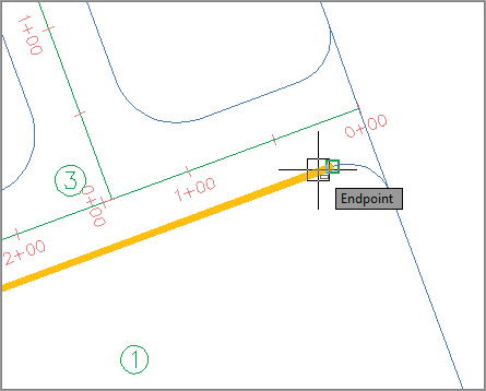
9. At the Select start point on frontage: prompt, use your Endpoint osnap to pick the point of curvature along the ROW parcel segment for Property 1 (see Figure 5-26).
Figure 5-26: Pick the point of curvature along the ROW parcel segment.

10. The parcel jig appears. Move your mouse slowly along the ROW parcel segment, and notice that the parcel jig follows the parcel segment. At the Select end point on frontage: prompt, use your Endpoint osnap to pick the point of curvature along the ROW parcel segment for Property 1 (see Figure 5-27).
Figure 5-27: Allow the parcel-creation jig to follow the parcel segment, and then pick the point of curvature along the ROW parcel segment.
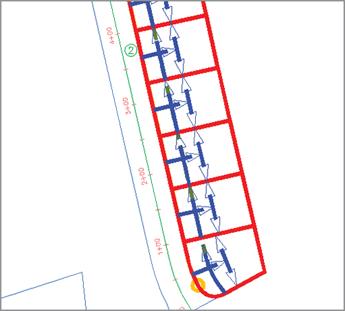
11. At the Specify angle or [Bearing/aZimuth]: prompt, enter 90↵. Notice the preview (see Figure 5-28).
Figure 5-28: A preview of the results of the automatic parcel layout
12. At the Accept result? [Yes/No] <Yes>: prompt, press ↵ to accept the default Yes.
13. At the Select parcel to be subdivided or [Pick]: prompt, press ↵, and then type X and press ↵ to exit the command.
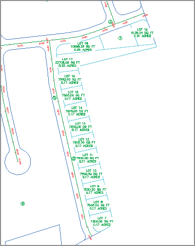
14. Your drawing should look similar to Figure 5-29. Note that Property 1 still exists among the newly defined parcels and has kept its original parcel style and area label style. Note the parcels at the north end that just don’t look right. We’ll address that a little later in this chapter.
Figure 5-29: The automatically created lots
Curves and the Frontage Offset
In most cases, the frontage along a building setback is graphically represented as a straight line drawn tangent or parallel to, and behind, the setback. When you specify a minimum width along a frontage offset (the building setback line) in the Parcel Layout Tools dialog, and when the lot frontage is curved, the distance you enter is measured along the curve. In most cases, this result may be insignificant, but in a large development, the error could be the defining factor in your decision to add or subtract a parcel from the development.
You may find this tool most useful when you’re re-creating existing lots or when you’d like to create a series of parallel lot lines with a known bearing.
Swing Line – Create Tool
The Swing Line – Create tool creates a “backward” attached parcel segment where the diamond-shaped grip appears not at the frontage but at a different location that you specify. The tool respects your minimum frontage, and it adjusts the frontage larger if necessary in order to respect your default area.
The Swing Line – Create tool is semiautomatic because it requires your input of the swing point location.
You may find this tool most useful around a cul-de-sac or in odd-shaped corners where you must hold frontage but have a lot of flexibility in the rear of the lot.