
A large part of a surveyor’s work involves querying lines and curves for their length, direction, and other parameters.
The Inquiry commands panel (Figure 2-30) is on the Analyze tab, and it makes a valuable addition to your Civil 3D and survey-related workspaces. Remember, panels can be dragged away from the Ribbon and set in the graphics environment much like a toolbar.
Figure 2-30: The Inquiry commands panel

The Inquiry tool (shown in Figure 2-31) provides a diverse collection of commands that assist you in studying Civil 3D objects. You can access the Inquiry tool by clicking the Inquiry Tool button on the Inquiry panel.
Figure 2-31: Choosing an Inquiry type from the Inquiry tool palette
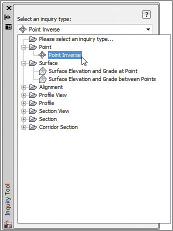
To use the Point Inverse option in the Inquiry commands, select the Point Inverse option as shown in Figure 2-32.
Figure 2-32: Point Inverse results

You can key in the point number or use the Pick In CAD icon to select the points you wish to examine.
The other Inquiry commands that are specific to Civil 3D are also handy to the survey process.
The List Slope tool provides a short command-line report that lists the elevations and slope of an entity (or two points) that you choose, such as a line or feature line.
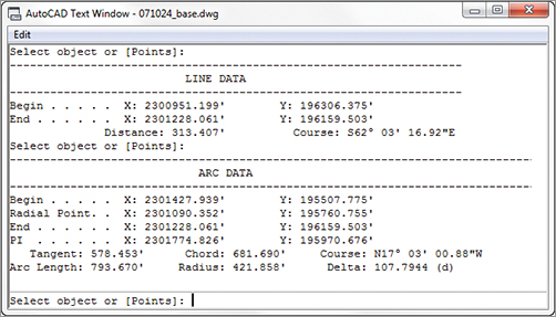
The Line And Arc Information tool provides a short report about the line or arc of your choosing (see Figure 2-33). This tool also works on parcel segments and alignment segments. Alternatively, you can type P for points at the command line to get information about the apparent line that would connect two points on screen.
Figure 2-33: Command-line results of a line inquiry and arc inquiry
Don’t Get Burned by AutoCAD Angles
Do not set base AutoCAD angular units to Surveyors Units. This setting may seem perfectly logical if you have been using base AutoCAD prior to using Civil 3D. However, this angular setting will end up confusing you more than helping you.
When looking for information about a line, use the Line and Arc tool mentioned in this section rather than the base AutoCAD LIST command. The Civil 3D Line and Arc tool (CGLIST) works on more object types and is not affected by rotated coordinate systems.
When entering angles in base AutoCAD, the full N50d10’10”E is needed to denote a bearing. In Civil 3D commands, N50.1010E will denote the same thing and is much faster to type. However, as every surveyor knows, there is a huge difference between 50.1010° and 50°10’10”.
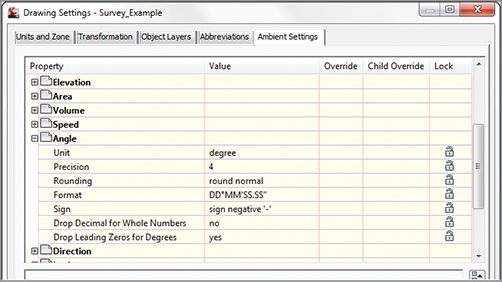
A setting you will want to change in your Civil 3D template is the angular entry method for general angles, as shown here. This setting mainly affects the Angle-Distance Transparent command. You will learn more about Civil 3D templates in Chapter 19, “Styles.”
Keep your base AutoCAD angular units set to Decimal Degrees to help you differentiate when you are in base AutoCAD angular entry and Civil 3D’s more surveyor-friendly angular entry.
The Angle Information tool lets you pick two lines (or a series of points on the screen). It provides information about the acute and obtuse angles between those two lines. Again, this also works for alignment segments and parcel segments.
The Continuous Distance tool provides a sum of distances between several points on your screen, or one base point and several points.
The Add Distances tool is similar to the Continuous Distance command, except the points on your screen do not have to be continuous.