
You build an assembly from the Home tab by choosing Assembly Create Assembly from the Create Design panel. The result is the main assembly baseline. This is the point on the assembly that gets “hooked in” to your design alignment and profile. A typical assembly baseline is shown in Figure 8-5.
Figure 8-5: Creating an assembly (left); an assembly baseline (right)
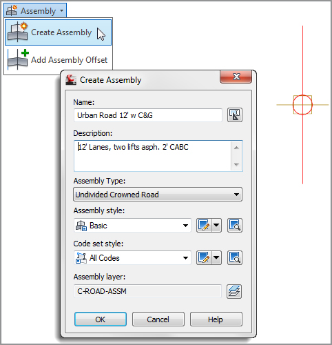
When an assembly is created, you have the option of telling Civil 3D what type of assembly this will be:
- Undivided Crowned Road
- Undivided Planar Road
- Divided Crowned Road
- Divided Planar Road
- Other
These categories will help the software determine the axis of rotation options in superelevation, if needed.
The Pre-Cooked Assemblies
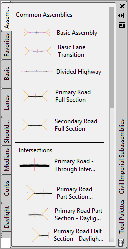
On the Assemblies tab of the tool palette, you will find a selection of predefined, completed assemblies (Figure 8-6). These are a great starting point for beginners who are looking for examples of how subassemblies are put together. There are examples of simple roadway sections as well as more advanced items, such as intersection and roundabout examples. To use one, click on the desired assembly, then click to place it in your drawing.
Figure 8-6: Predefined assemblies
Creating a Typical Road Assembly
The process for building an assembly requires the use of the Tool Palette feature and the AutoCAD Properties palette, both of which can be docked. You’ll quickly learn how to best orient these palettes with your limited screen real estate. If you run dual monitors, you may find it useful to place both of these palettes on your second monitor.
The exercise that follows builds a typical assembly using LaneOutsideSuper, UrbanCurbGutterGeneral, UrbanSidewalk, and DaylightMaxOffset subassemblies (see Figure 8-7).
Figure 8-7: A typical road assembly
Let’s have a more detailed look at each component you’ll use in the following exercise. A quick peek into the subassembly Help will give you a breakdown of attachment options; input parameters; target parameters; output parameters; behavior; layout mode operation; and the point, link, and shape codes.
The LaneOutsideSuper Subassembly The LaneOutsideSuper subassembly is the best all-purpose subassembly for lanes. It can superelevate if needed, and allows for up to four layers of materials. The default width of 12′ (3.6m) can be adjusted in the parameters or can be used with an offset alignment to control its width. (See Figure 8-8.)
Figure 8-8: The LaneOutsideSuper subassembly
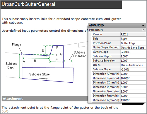
The UrbanCurbGutterGeneral Subassembly The UrbanCurbGutterGeneral subassembly (Figure 8-9) is another standard component that creates an attached curb and gutter. Looking into the subassembly Help, you’ll see a diagram of the BasicCurbandGutter with callouts for its seven parameters: side; insertion point; gutter width and slope; and curb height, width, and depth. You can adjust these parameters to match many standard curb-and-gutter configurations.
Figure 8-9: The UrbanCurbGutterGeneral subassembly

The UrbanSidewalk Subassembly The UrbanSidewalk subassembly (Figure 8-10) creates a sidewalk and terrace buffer strips. The Help file lists the following five parameters for the UrbanSidewalk subassembly: side, width, depth, buffer width 1, and buffer width 2. These parameters let you adjust the sidewalk width, material depth, and buffer widths to match your design specification. You can adjust the slope for the entire length of the subassembly as a unit, but not the individual segments.
Figure 8-10: The UrbanSidewalk subassembly

The UrbanSidewalk subassembly can return quantities of concrete (or other sidewalk construction material) but not gravel bedding or other advanced material layers.
The DaylightMaxOffset Subassembly The DaylightMaxOffset subassembly (Figure 8-11) is a nice “starter” for creating simple, single-slope daylight instructions for your corridor. The maximum offset in the parameters is measured from the baseline (in our example, the centerline of the road). The slope will attempt a default of 4:1, but will adjust if it needs to in order to keep inside your specified maximum offset.
Figure 8-11: The DaylightMaxOffset Subassembly

What’s With the Funny Names?
You’ll notice that all subassemblies have names with no spaces. This is because of the underlying .NET coding that makes up a subassembly. When you place one of these in your project it will retain the name from the tool palette and place a number after it to ensure unique names for all subassemblies in your drawing. Later in this chapter, you’ll see how to rename them to something more user-friendly!
In the following exercise, you’ll build a typical road assembly using these subassemblies. Follow these steps:
1. Create a new drawing from the Civil 3D template of your choice. Be sure your Civil 3D tool palette is showing the subassembly set appropriate for your drawing units (or you may end up with monster 12 meter lanes!). Change the active tool palette by right-clicking the edge of the tool palette, as shown in Figure 8-12.
Figure 8-12: Right-click the edge of the tool palette to change assembly sets if needed.
2. Change to the Home tab and choose Assembly Create Assembly from the Create Design panel. The Create Assembly dialog opens.
3. Enter Urban 14′ Single-Lane (or Urban 4.5m Single-Lane) in the Name text box. Set the Assembly Type to Undivided Crowned Road. Make sure the Assembly Style text box is set to Basic and the Code Set Style text box is set to All Codes. Click OK.
4. Pick a location in your drawing for the assembly—somewhere in the center of your screen is fine.
5. Locate the Lanes tab on the tool palette. Position the palette on your screen so that you can clearly see the assembly baseline.
6. Click the LaneOutsideSuper button on the tool palette. The AutoCAD Properties palette appears. Position the palette on your screen so that you can clearly see both the assembly baseline and the Lanes tool palette.
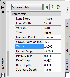
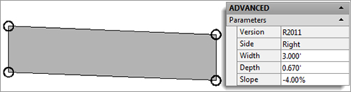
7. Locate the Advanced-Parameters section on the Design tab of the AutoCAD Properties palette (Figure 8-13). This section lists the LaneOutsideSuper parameters. Make sure the Side parameter says Right, set the Crown Point on Inside to Yes, and change the Width parameter to 14′ (4.5 m). Your Properties palette should resemble Figure 8-13.
Figure 8-13: The Advanced Parameters inside the Properties palette

8. The command line states Select marker point within assembly or [RETURN for Detached]: Click anywhere on the red assembly marker to place the first lane.
9. Switch to the Curbs tab in the subassemblies palette.
10. Click the UrbanCurbGutterGeneral button on the tool palette. The Advanced section of the AutoCAD Properties palette’s Design tab lists the UrbanCurbGutterGeneral parameters. Verify the Side parameter is set to Right; you will accept the parameter defaults, so no changes are needed.
11. The command line states Select marker point within assembly or [RETURN for Detached]:. Click the circular point marker located at the top right of the LaneOutsideSuper subassembly. This marker represents the top-right edge of pavement (see Figure 8-14).
Figure 8-14: The UrbanCurbGutterGeneral subassembly placed on the LaneOutsideSuper subassembly

If You Goof…
Often, the first instinct when a subassembly is misplaced is to Undo or erase the wayward piece. However, if you have spent lots of time diligently tweaking parameters, there is a way to fix things without redoing the subassembly. Select the errant subassembly and use the Move To Assembly option in the context tab. Use this instead of the base-AutoCAD Move tool to get the best results. Using regular AutoCAD Move may cause unexpected results in the corridor.
If you placed everything correctly but forgot to change a parameter or two, there’s an easy fix for that, too. Cancel out of any active subassembly placement and select the subassembly you wish to change. Use good-old AutoCAD properties to quickly access the parameters.
Most subassembly parameters can be changed from base-AutoCAD properties. For more heavy-duty modifications (such as side or renaming), you will want to get into the Subassembly Properties discussed later in this chapter.
12. In the Curbs tab, click the UrbanSidewalk button on the tool palette. In the Advanced section of the Design tab on the AutoCAD Properties palette, verify the Side parameter is set to Right, the Sidewalk Width parameter to 5′ (1.5 m), and the Inside Boulevard Width and Outside Boulevard Width parameters to 2′ (0.7 m).
13. The command line states Select marker point within assembly or [RETURN for Detached]:. Click the circular point marker on the UrbanCurbGutterGeneral subassembly that represents the top rear of the curb to attach the UrbanSidewalk subassembly (see Figure 8-15).
Figure 8-15: The BasicSidewalk subassembly placed on the UrbanCurbGutterGeneral subassembly

14. Switch to the Daylight tab on the Civil subassemblies palette. Select the DaylightMaxOffset subassembly. In the Advanced-Parameters area, set the Max Offset from Baseline to 50′ (17 m).
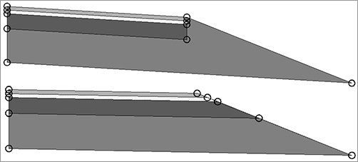
15. The command line states Select marker point within assembly or [RETURN for Detached]:. Select the circular marker on the outermost point of the sidewalk subassembly. Your drawing should now resemble Figure 8-16.
Figure 8-16: The complete right side of the assembly with DaylightMaxOffset

16. To complete the left side, you will use the Mirror Subassemblies command, as shown in Figure 8-17. Select all four subassemblies to the right of the baseline.
Figure 8-17: The context tab with subassembly modification tools
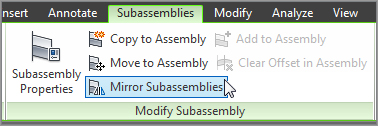
17. The context tab will show a variety of tools, including Mirror Subassemblies (Figure 8-17). Select Mirror Subassemblies, and then click the assembly baseline. Your assembly should now resemble Figure 8-7 from earlier in the chapter.
You have now completed a typical road assembly. Save your drawing if you’d like to use it in a future exercise.
Getting the Most from Subassembly Help
Each subassembly is capable of accomplishing different tasks in your design. There is no way to tell just by looking at the icon all the acrobatics that an assembly can do. For a detailed rundown of each parameter, and what can be done with a subassembly, you will need to pop into the help files.
Before we go into the help files, let’s dig deeper into the anatomy of a subassembly. A subassembly is made up of three basic parts: links, marker points, and shapes, as shown in Figure 8-18. Each piece plays a role in your design and is used for different purposes at each stage of the design process.
Figure 8-18: Schematic showing parts of an assembly
Links
Links are the linear components to your assembly. A link usually represents the top or bottom of a material but can also be used as a spacer between subassemblies.
Links can have codes assigned to them that Civil 3D uses to build the design. Think of these codes as nicknames. In the example assembly you created in the previous exercise, you used a sidewalk subassembly. On the sidewalk the topmost link has the codes Top and Sidewalk (Figure 8-19a); on the lane subassembly the topmost codes are Top and Pave (Figure 8-19b).
Links will be your primary source of data when creating proposed surfaces from your corridors.
Figure 8-19: Link codes on the UrbanSidewalk Subassembly (a) and link codes on the LaneOutsideSuper Subassembly (b)


Marker Points
Marker points are located at the endpoints of every link and usually are represented by the circles you see on the subassemblies as shown in Figures 8-20a and 8-20b. As you experienced in the previous exercise, the markers are used in assembly creation to “click” subassemblies together.
When a corridor is created, the marker points show real might. Markers are used as “hooks” to attach to alignments and/or profiles, known as targets, as discussed in Chapter 9, “Basic Corridors.” Markers are the starting point for feature lines generated by the corridor, which are used for a variety of purposes that we will discuss in the upcoming chapters.
Figure 8-20: Marker point codes on the UrbanSidewalk subassembly (a) and marker point codes on the LaneOutsideSuper subassembly (b)


Shapes
Shapes are the areas inside a closed formation of links. For example, Figure 8-21a and Figure 8-21b show different subassemblies with shape codes labeled. Shapes are used in end-area material quantity calculations. At the time an assembly is created, you do not need to consider what material these shapes represent. After your corridor is complete, you will specify what materials the codes represent upon computing materials.
Jumping into Help
Subassembly Help is extremely—well, helpful! There are many doors into the help files, including from the Corridor Modeling Catalog as you saw earlier. Right-click on any subassembly in the tool palette and select Help as shown in Figure 8-22.
Figure 8-21: Shape codes on the UrbanSidewalk Subassembly (a) and shape codes on the LaneOutsideSuper subassembly (b)
Figure 8-22: Getting to the subassembly help file for UrbanCurbGutterGeneral

Help 101
When you access Subassembly Help, it will take you to the help file specific to the subassembly you are working with. At the top, you will see a diagram showing the location of the numeric parameters.
For most subassemblies, the default attachment point will be the topmost-inside marker point. The help file will tell you if this differs for the subassembly you are looking at (Figure 8-23). Scroll further down to see detailed explanation of every parameter.
Figure 8-23: The top portion of Subassembly Help shown with subassembly parameters
Target Parameters and Output Parameters
Target parameters are a listing of what targets can be set for a subassembly. In other words, if a marker point can be “hooked” to something (i.e., an offset alignment), the target parameters will tell you what to look for in the corridor targets and the type of object it can hook. The help file will also tell you whether the target is optional or required. We will get into target parameters and setting targets in Chapter 9.
Output parameters are values calculated on corridor build, such as the cross-slope of a lane. In several subassemblies, there is an advanced option called Parameter Reference that can use output parameters instead of a constant as a slope.
Reading a Coding Diagram
The coding diagram gives a list of all the codes used on the subassembly you are working with. Every named marker point, link, and shape is listed here. Not all subassembly components have explicit names, such as L10 shown in Figure 8-24. If the marker point, shape, or link is not included in the table, it is considered uncoded.
Figure 8-24: Coding diagram and name table for UrbanCurbGutterGeneral

Commonly Used Subassemblies
Once you gain some skills in building assemblies, you can explore the Corridor Modeling Catalog to find subassemblies that have more advanced parameters so that you can get more out of your corridor model. For example, if you must produce detailed schedules of road materials such as asphalt, coarse gravel, fine gravel, subgrade material, and so on, the catalog includes lane subassemblies that allow you to specify those thicknesses for automatic volume reports.
The following section includes some examples of different components you can use in a typical road assembly. Many more alternatives are available in the Corridor Modeling Catalog. The Help file provides a complete breakdown of each subassembly in the catalog; you’ll find this useful as you search for your perfect subassembly.
Each of these subassemblies can be added to an assembly using exactly the same process specified in the first exercise in this chapter. Choose your alternative subassembly instead of the basic parts specified in the exercise, and adjust the parameters accordingly.
Common Lane Subassemblies
Although the LaneOutsideSuper subassembly is suitable for many roads, you may need different road lanes for your locality or design situation.
LaneInsideSuper On a two-lane, undivided highway there is practically no difference between the LaneOutsideSuper and LaneInsideSuper. However, when a divided highway with superelevation is created, LaneInsideSuper is needed to control the superelevation rate of the lanes closest to the median, as shown in Figure 8-25.
Figure 8-25: Use of LaneInsideSuper and LaneOutsideSuper in a divided highway
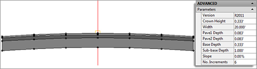
LaneParabolic The LaneParabolic subassembly (Figure 8-26) is used for road sections that require a parabolic lane in contrast to the linear grade of LaneOutsideSuper. The LaneParabolic subassembly also adds options for two pavement depths and a base depth. This is useful in jurisdictions that require two lifts of asphalt and granular sub-base material. Taking advantage of these additional parameters gives you an opportunity to build corridor models that can return more detailed quantity takeoffs and volume calculations.
Figure 8-26: The LaneParabolic subassembly and parameters
Note that the LaneParabolic subassembly doesn’t have a Side parameter. The parabolic nature of the component results in a single attachment point that would typically be the assembly centerline marker. Keep in mind that subassemblies are AutoCAD objects and, therefore, can be moved to the right or to the left (as well as up and down) when specifications require design profiles along the top back of curb as opposed to the centerline of a travel way.
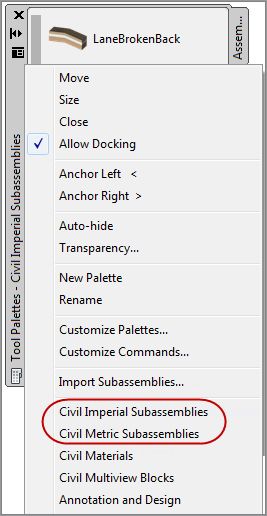
LaneBrokenBack If your design calls for multiple lanes, and those lanes must each have a unique slope, investigate the LaneBrokenBack subassembly (Figure 8-27). This subassembly provides parameters to change the road-crown location and specify the width and slope for each lane. Like LaneParabolic, the LaneBrokenBack subassembly provides parameters for additional material thicknesses.
Figure 8-27: The LaneBrokenBack subassembly and parameters

The LaneBrokenBack subassembly, like LaneOutsideSuper, allows for the use of target alignments and profiles to guide the subassembly horizontally and/or vertically.
Common Shoulder and Curb Subassemblies
There are many types of curbs, and the UrbanCurbGutterGeneral subassembly can’t model them all. Sometimes you may need a mountable curb, or perhaps you need a shoulder instead. In those cases, the Corridor Modeling Catalog provides many alternatives:
UrbanCurbGutterValley (1, 2, or 3) The UrbanCurbGutterValley subassemblies are great if you need mountable curbs (Figure 8-28). UrbanCurbGutterValley 1, 2, and 3 vary slightly in how they handle the sub-base slope. UrbanCurbGutterValley 1 also differs because it comes to a point instead of offering a width at the top of curb.
Figure 8-28: The UrbanCurbGutterValley subassemblies

BasicShoulder BasicShoulder (see Figure 8-29) is another simple yet effective subassembly for use with road sections that require a shoulder. The predefined shape for this subassembly is Pave1, which is good if you are planning to treat this as a paved shoulder and quantify the material with the Pave1 from a lane.
Figure 8-29: The BasicShoulder subassembly and parameters
ShoulderExtendSubbase and ShoulderExtendAll Shoulders that can work with your lanes in a superelevation situation, as these two do, are extremely helpful. These two subassemblies (shown in Figures 8-30a and 8-30b) will “play nice” with your breakover removal settings, as you will see in Chapter 11, “Superelevation.”
Figure 8-30: ShoulderExtendSubbase subassembly (a) and ShoulderExtendAll subassembly (b)
Editing an Assembly
As you saw earlier in this chapter, good-old AutoCAD properties are an option for changing subassembly parameters for one or more subassemblies of the same type. However, there are a handful of settings that can only be controlled in the Civil 3D Subassembly Properties. For example, the side (left or right) is an item must be changed in the Subassembly Properties.
Editing a Single Subassembly

Once your assembly is created, you can edit individual subassemblies as follows:
1. Pick the subassembly you’d like to edit. This will bring up the context tab.
2. Select the Subassembly Properties option from the Modify Subassembly panel.
3. The Subassembly Properties dialog appears. Click the Subassembly Help button at the bottom right of the dialog if you want to access the help page that gives detailed information about the use of this particular subassembly.
4. Switch to the Parameters tab to access the same parameters you saw in the AutoCAD Properties palette when you first placed the subassembly.
5. Click inside any field on the Parameters tab to make changes.
Editing the Entire Assembly

Sometimes it’s more efficient to edit all the subassemblies in an assembly at once. To do so, pick the assembly baseline marker, or any subassembly that is connected to the assembly you’d like to edit. This time, select the Assembly Properties option from the Modify Assembly panel.
Renaming the Assembly
The Information tab on the Assembly Properties dialog gives you an opportunity to rename your assembly and provide an optional description. It is good practice to be consistent and detailed in your assembly names (for example, Divided 4-Lane 12′ w Paved Shoulder). With informative assembly names, you will eliminate much of the guesswork when it comes to building corridors.
Changing Parameters
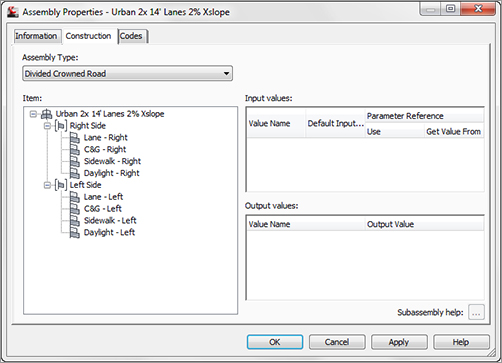
The Construction tab on the Assembly Properties dialog houses each subassembly and its parameters. You can change the parameters for individual subassemblies by selecting the subassembly on the left side of the Construction tab and changing the desired parameter on the right side.
Renaming Groups and Subassemblies
Note that the left side of the Construction tab displays a list of groups. Under each group is a list of the subassemblies in use in your assembly. A new group is formed every time a subassembly is connected directly to the assembly marker.
For example, in Figure 8-31 you see Group - (1). The first subassembly under Group - (1) is LaneOutsideSuper - (37). If you dig into its parameters on the right side of the dialog, you’ll learn that this lane is attached to the right side of the assembly marker, a UrbanCurbGutterGeneral is attached to right side of the LaneOutsideSuper, and a UrbanSidewalk is attached to the right side of the UrbanCurbGutterGeneral. The next group, Group - (3), is identical but attached to the left side of the assembly marker.
Figure 8-31: The Construction tab shows the default group and subassembly naming.

The automatic naming conventions are somewhat cryptic, and it is convenient not to have to dig into the subassembly parameters to determine which side of the assembly a certain group is on. Later, when you’re making complex corridors, you’ll be provided with a list of subassemblies to choose from; it’s certainly easier to figure out which LaneOutsideSuper you need to choose when your choice is Lane - Right as opposed to LaneOutsideSuper - (37). Therefore, it’s in your best interest to rename your subassemblies once you’ve built your assembly.
You can rename both groups and subassemblies on the Construction tab of the Assembly Properties dialog by double-clicking on the group or subassembly you wish to rename.
There is no official best practice for renaming your groups and subassemblies, but you may find it useful to designate what type of subassembly it is, what side of the assembly it falls on, and other distinguishing features (see Figure 8-32). For example, if a lane is to be designated as a transition lane or a generic link used as a ditch foreslope, it would be useful to name them descriptively.
Figure 8-32: The Construction tab showing renamed groups and subassemblies
Creating Assemblies for Nonroad Uses
There are many uses for assemblies and their resulting corridor models aside from road sections. The Corridor Modeling Catalog also includes components for retaining walls, rail sections, bridges, channels, pipe trenches, and much more. In Chapter 9, you’ll use a channel assembly and a pipe-trench assembly to build corridor models. Let’s investigate how those assemblies are put together by building a channel assembly for a stream section:
1. Create a new drawing from the DWT of your choice, or continue working in your drawing from the first exercise in this chapter.
2. Change to the Home tab and choose Assembly Create Assembly from the Create Design panel. The Create Assembly dialog opens.
3. Enter Channel in the Name text box. Confirm that the Assembly Style text box is set to Basic and that Code Set Style is set to All Codes. Click OK.
4. Specify a location in your drawing for the assembly. Somewhere in the center of your screen where you have room to work is fine.
5. Locate the Trench Pipes tab on the tool palette. Position the palette on your screen so that you can clearly see the assembly baseline.
6. Click the Channel button on the tool palette. The AutoCAD Properties palette appears.
7. Locate the Advanced section of the Design tab on the AutoCAD Properties palette. You’ll place the channel with its default parameters and make adjustments through the Assembly Properties dialog, so don’t change anything for now. Note that there is no Side parameter. This subassembly will be centered on the assembly marker.
8. The command line states Select marker point within assembly or [RETURN for Detached]:. Pick the assembly center-point marker, and a channel is placed on the assembly (see Figure 8-33).
Figure 8-33: The Channel subassembly placed on the assembly center point marker

9. Press Esc to leave the assembly-creation command and dismiss the palette.
10. Select the center assembly baseline marker and select Assembly Properties from the Modify Assembly panel.
11. The Assembly Properties dialog appears. Switch to the Construction tab.
12. Select the Channel entry on the left side of the dialog (under the Group). Click the Subassembly Help button located at bottom right in the dialog’s Construction tab.
13. The Subassembly Reference portion of the AutoCAD Civil 3D 2012 Help file appears. Familiarize yourself with the diagram and input parameters for the Channel subassembly. Especially note the Attachment Point, Bottom Width, Depth, and Sideslope parameters. The attachment point indicates where your baseline alignment and profile will be applied.
14. Minimize the Help file.
15. To match the engineer’s specified design, you need a stream section 6′ (2 m) deep with a 3′ (1 m)-wide bottom, 1:1 sideslopes, and no backslopes. Change the following parameters in the Assembly Properties dialog:
- Bottom Width: 3′ (1 m)
- Depth: 6′ (2 m)
- Left and Right Backslope Width: 0′ (0 m)
- Sideslope: 1:1
16. Click OK, and confirm that your completed assembly looks like Figure 8-34.
Figure 8-34: A completed channel assembly

A Pipe Trench Assembly
Projects that include piping, such as sanitary sewers, storm drainage, gas pipelines, or similar structures, almost always include trenching. The trench must be carefully prepared to ensure the safety of the workers placing the pipe, as well as provide structural stability for the pipe in the form of bedding and compacted fill.
The corridor is an ideal tool for modeling pipe trenching. With the appropriate assembly combined with a pipe-run alignment and profile, you can not only design a pipe trench but also use cross-section tools to generate section views, materials tables, and quantity takeoffs. The resulting corridor model can also be used to create a surface for additional analysis.
The following exercise will lead you through building a pipe trench corridor based on an alignment and profile that follow a pipe run, and a typical trench assembly:
1. Create a new drawing using the DWT of your choice, or continue working in your drawing from the previous exercise.
2. Change to the Home tab and choose Assembly Create Assembly from the Create Design panel. The Create Assembly dialog opens.
3. Enter Pipe Trench in the Name text box to change the assembly’s name. Confirm that the Assembly Style text box is set to Basic and Code Set Style is set to All Codes. Click OK.
4. Pick a location in your drawing for the assembly. Somewhere in the center of your screen where you have room to work is fine.
5. Locate the Trench Pipes tab on the tool palette. Position the palette on your screen so that you can clearly see the assembly baseline.
6. Click the TrenchPipe1 button on the tool palette. The AutoCAD Properties palette appears. Position the AutoCAD Properties palette on your screen so that you can clearly see both the assembly baseline and the tool palette.
7. Locate the Advanced section of the Design tab on the AutoCAD Properties palette. This section lists the TrenchPipe1 parameters. You’ll place TrenchPipe1 with its default parameters and make adjustments through the Assembly Properties dialog, so don’t change anything for now. Note that there is no Side parameter. This subassembly will be placed centered on the assembly marker.
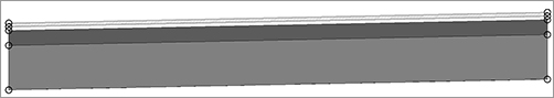
8. The command line states Select marker point within assembly or [RETURN for Detached]:. Pick the assembly center-point marker. A TrenchPipe1 subassembly is placed on the assembly as shown here:

9. Press Esc to leave the assembly-creation command and dismiss the AutoCAD Properties palette.
10. Select the assembly marker and select Assembly Properties from the Modify Assembly panel.
11. The Assembly Properties dialog appears. Switch to the Construction tab.
12. Select the TrenchPipe1 assembly entry on the left side of the dialog. Click the Subassembly Help button located at the bottom right.
13. The Subassembly Reference portion of the AutoCAD Civil 3D 2012 Help file appears. Familiarize yourself with the diagram and input parameters for the TrenchPipe1 subassembly. In this case, the profile grade line will attach to a profile drawn to represent the pipe invert. Because the trench will be excavated deeper than the pipe invert to accommodate gravel bedding, you’ll use the bedding depth parameter in a moment. Also note under the Target Parameters that this subassembly needs a surface target to determine where the sideslopes terminate.
14. Minimize the Help file.
15. To match the engineer’s specified design, the pipe trench should be 3′ (1 m) deep and 4′ (1.3 m) wide with 2:1 sideslopes and 1′ (0.3 m) of gravel bedding. Change the following parameters in the Assembly Properties dialog:
- Width: 4′ (1.3 m)
- Sideslope: 2:1
- Bedding Depth: 1′ (0.3m)
- Offset To Bottom: 3′ (1 m)
16. Click OK.
17. Confirm that your completed assembly looks like the graphic shown here, and save your drawing.

This assembly will be used to build a pipe-trench corridor in Chapter 9.