
Despite the more than 100 subassemblies available in the Corridor Modeling Catalog, sometimes you may not find the perfect component. Perhaps none of the channel assemblies exactly meet your design specifications, and you’d like to make a more customized assembly, or neither of the sidewalk subassemblies allows for the proper boulevard slopes. Maybe you’d like to try to do some preliminary lot grading using your corridor, or mark a certain point on your subassembly so that you can extract important features easily.
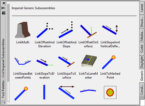
You can handle most of these situations by using subassemblies from the Generic Subassembly Catalog (see Figure 8-35). These simple and flexible components can be used to build almost anything, although they lack the coded intelligence of some of the more intricate assemblies (such as knowing if they’re paved, grass, or similar, and understanding things like sub-base depth, and so on).
Figure 8-35: The Generic Subassembly tool palette
Using Generic Links
Let’s look at two examples where you might take advantage of generic links.
The first example involves the typical road section you built in the first exercise in this chapter. You saw that UrbanSidewalk doesn’t allow for differing cross-slopes. If you need a 3′ (1 m)-wide terrace with a 3 percent slope, and then a 5′ (1.5 m) sidewalk with a 2 percent slope, followed by another buffer strip that is 6′ (2 m) wide with a slope of 5 percent, you can use generic links to assist in the construction of the proper assembly:
1. Open the Subassembly Practice.dwg file (which you can download from this book’s web page).
2. In Prospector, locate and expand the assemblies group. Right-click on Sidewalk With Generic Links and select Zoom To.
3. Locate the Generic tab on the tool palette. Position the palette on your screen so that you can clearly see the assembly baseline.
4. Click the LinkWidthandSlope subassembly, and the AutoCAD Properties dialog appears. Position the dialog on your screen so that you can clearly see both the assembly baseline and the tool palette.
5. Scroll down to the Advanced Parameters section of Properties and change the parameters as follows to create the first buffer strip:
- Side: Right
- Width: 3′ (1 m)
- Slope: 3%
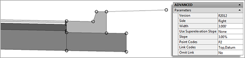
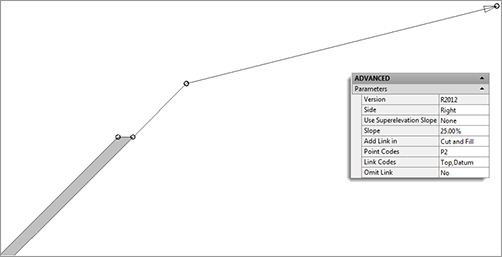
6. The command line states Select marker point within assembly or [RETURN for Detached]:. Select the circular point marker on the right UrbanCurbGutterGeneral subassembly, which represents the top back of the curb. A Link subassembly appears, as shown in Figure 8-36.
Figure 8-36: The Generic Link subassembly (parameters shown for illustration)
7. Switch to the Curbs tab of the tool palette. Click the UrbanSidewalk button.
8. In the Advanced Parameters area of Properties, change the parameters as follows to create the sidewalk:
- Side: Right
- Sidewalk Width: 5′ (1.5 m)
- Slope: 2%
- Inside Boulevard Width: 0′
- Outside Boulevard Width: 0′
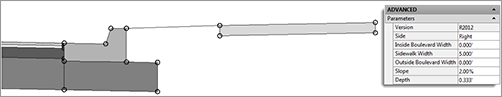
9. The command line states Select marker point within assembly or [RETURN for Detached]:. Select the circular point marker on the right LinkWidthandSlope subassembly. An UrbanSidewalk subassembly appears, as shown in Figure 8-37.
Figure 8-37: The UrbanSidewalk subassembly (parameters shown for illustration)
10. Switch to the Generic tab of the tool palette. Click the LinkWidthandSlope button, and the AutoCAD Properties palette appears. Position the palette on your screen so that you can still see the assembly baseline and the tool palette.
11. In the Advanced Parameters area of Properties, change the parameters as follows to create the second buffer strip:
- Side: Right
- Width: 6′ (2 m)
- Slope: 5%
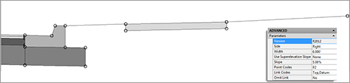
Your drawing should now look like Figure 8-38.
Figure 8-38: The sidewalk and terrace strips (parameters shown for illustration)
12. Select the two generic links and the sidewalk assembly.
13. Select Mirror Subassemblies from the Modify Subassembly panel. The command line displays Select marker point within assembly:.
14. Select the marker point on the left back of curb. The completed assembly should look like Figure 8-39.
Figure 8-39: The completed assembly

15. Save the drawing if you’d like to use it in a future exercise.
You’ve now created a custom sidewalk terrace for a typical road.
Daylighting with Generic Links
The second example involves the channel section you built earlier in this chapter. This exercise will lead you through using the LinkSlopetoSurface generic subassembly, which will provide a surface target to the Channel assembly that will seek the target assembly at a 25 percent slope. For more information about surface targets, see Chapters 9 and 10. Follow these steps:
1. Continue working in, or open, the Subassembly Practice.dwg file (which you can download from this book’s web page). You do not need to have the previous exercise completed to continue.
2. In Prospector, locate and expand the assemblies group. Right-click on Channel With Link To Surface and select Zoom To.
3. Locate the Generic tab on the tool palette.
4. Click the LinkSlopetoSurface button.
5. In the Advanced Parameters area of Properties, change the parameters as follows to create a surface target link:
- Side: Right
- Slope: 25%
6. The command line states Select marker point within assembly or [RETURN for Detached]:. Click the circular point marker at the upper right on the Channel subassembly that is farthest away. A surface target link appears (see Figure 8-40).
Figure 8-40: LinkSlopetoSurface subassembly (parameters shown for illustration)
7. To complete the left side of the assembly, repeat steps 4 through 6, and change the Side parameter to the Left option.
8. The completed assembly should look like Figure 8-41.
Figure 8-41: The completed Channel assembly
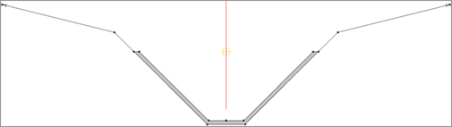
Adding a surface link to a Channel assembly provides a surface target for the assembly. Now that you’ve added the LinkSlopetoSurface, you can specify your existing ground as the surface target, and the subassembly will grade between the top of the bank and the surface for you. You can achieve additional flexibility for connecting to existing ground with the more complex Daylight subassemblies, as discussed in the next section.
Working with Daylight Subassemblies
In previous examples we worked with daylight subassemblies, but it is now time to take a closer look at what they can do for us.
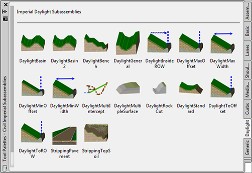
A daylight subassembly contains the instructions to Civil 3D as to how it is to extend a link to a target surface. The instructions might include a ditch or berm before looking for existing ground. Others provide a straight shot but with contingencies for certain design conditions. Figure 8-42 shows the many options you have for adding a daylight to an assembly.
Figure 8-42: Daylight subassemblies in the Corridor tool palette
In the following exercise, you’ll use the DaylightInsideROW subassembly. This subassembly contains parameters for specifying the maximum distance from the centerline or offset alignments. If the 4:1 slope hits the surface inside the ROW, no adjustment is made to the slope. If 4:1 causes the daylight to hit outside of the ROW, the slope adjusts to stay inside the specified location:
1. Continue working in, or open the Subassembly Practice.dwg file (which you can download from this book’s web page). You do not need to have the previous exercise completed to continue.
2. In Prospector, locate and expand the assemblies group. Right-click on Add Daylight Subassembly and select Zoom To.
3. Locate the Daylight tab on the tool palette.
4. Click the DaylightInsideROW button on the tool palette.
5. In the Advanced Parameters area of Properties, change the following parameters to create the daylight as required:
ROW Offset from Baseline: 33′ (10 m)
Leave all other parameters at their default values.
6. The command line states Select marker point within assembly or [RETURN for Detached]:. Select the circular point marker on the farthest right link.
7. Stay in the subassembly placement, but change the following parameter before placing the left side:
ROW Offset from Baseline: -33′ (-10 m)
Notice there is no Left or Right parameter. The negative value in the ROW Offset From Baseline parameter is what tells Civil 3D the daylight is to the left. You can now dismiss the Properties palette.
8. Pick the DaylightInsideROW subassembly, and then choose Subassembly Properties from the Modify Subassembly panel.
9. Switch to the Parameters tab in the Subassembly Properties dialog.
10. Click the Subassembly Help button in the lower-right corner. The Subassembly Reference opens in a new window. Familiarize yourself with the options for the DaylightInsideROW subassembly, especially noting the optional parameters for a lined material, a mandatory daylight surface target, and an optional ROW offset target that can be used to override the ROW offset specified in the parameters.
11. Minimize the Subassembly Reference window. The completed assembly should look like Figure 8-43.
Figure 8-43: An assembly with the daylight subassembly attached to each side (parameters shown for illustration)

When to Ignore Daylight Input Parameters
The first time you attempt to use many Daylight subassemblies, you may become overwhelmed by the sheer number of parameters.
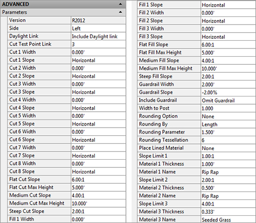
The good news is that many of these parameters are unnecessary for most uses. For example, many Daylight subassemblies, such as DaylightGeneral (shown above), include multiple cut-and-fill widths for complicated cases where the design may call for test scenarios. If your design doesn’t require this level of detail, leave those parameters set to zero.
Some Daylight subassemblies include guardrail options. If your situation doesn’t require a guardrail, leave the default parameter set to the Omit Guardrail option and ignore it from then on. Another common, confusing parameter is Place Lined Material, which can be used for riprap or erosion-control matting. If your design doesn’t require this much detail, ensure that this parameter is set to None, and ignore the thickness, name, and slope parameters that follow.
If you’re ever in doubt about which parameters can be omitted, investigate the Help file for that subassembly.
Alternative Daylight Subassemblies
At least a dozen Daylight subassemblies are available, varying from a simple cut-fill parameter to a more complicated benching or basin design. Your engineering requirements may dictate something more challenging than the exercise in this section. Here are some alternative Daylight subassemblies and the situations where you might use them. For more information on any of these subassemblies and the many other daylighting choices, see the AutoCAD Civil 3D 2012 Subassembly Reference in the help file.
DaylightToROW The DaylightToROW subassembly (Figure 8-44a) differs slightly from the DaylightInsideROW (Figure 8-44b). DaylightToROW constantly adjusts the slope to stay a certain distance away from your ROW, as specified by the Offset Adjustment input parameter. For example, you can have a ROW alignment specified, but use this subassembly to tell Civil 3D to always stay 3′ inside the ROW line.
Figure 8-44: Daylight to ROW (a) and Daylight Inside ROW (b) subassemblies
BasicSideSlopeCutDitch In addition to including cut-and-fill parameters, the BasicSideSlopeCutDitch subassembly (see Figure 8-45) creates a ditch in a cut condition. This is most useful for road sections that require a roadside ditch through cut sections but omit it when passing through areas of fill. If your corridor model is revised in a way that changes the location of cut-and-fill boundaries, the ditch will automatically adjust.
Figure 8-45: The BasicSideSlopeCutDitch subassembly in layout mode

Several subassemblies display the “LayoutMode” text on the design assembly. This will not display on the completed corridor.
DaylightBasin Many engineers must design berms to contain roadside swales when the road design is in the fill condition. The process for determining where these berms are required is often tedious. The DaylightBasin subassembly (see Figure 8-46) provides a tool for automatically creating these “false berms.” The subassembly contains parameters for the specification of a basin (which can be easily adapted to most roadside ditch cross sections as well) and parameters for containment berms that appear only when the subassembly runs into areas of roadside cut.
Figure 8-46: The DaylightBasin subassembly
