
As you get to know Civil 3D better, you will want it to do more for you. With the tools you are given and your own creativity and problem-solving skills, Civil 3D can create some serious designs. Offset assemblies and marked point assemblies are weapons in your arsenal of awesome.
Offset Assemblies
Offset assemblies are an advanced option when you want to model a coordinating structure whose design is related to the main assembly. An example of where an offset assembly would be helpful is a main road adjacent to a meandering bike path. The bike path generally follows the main road, but its alignment is not always parallel and the profile might be altogether different. Figure 8-47 shows what the assembly for a bike path to the left of a road would look like.
Figure 8-47: An example of an assembly with an offset to the left representing a bike path

To use an offset assembly, go to Home Assembly Add Assembly Offset. You will be prompted to select the main assembly and place the offset in the graphic. The location of the offset assembly in relation to the main assembly will have no effect on the final design.
Once the offset assembly is placed, the construction of an offset is identical to any other assembly. We will use an example of an assembly with an offset in Chapter 10, “Advanced Corridors, Intersections and Roundabouts.”
Marked Points and Friends
The marked point assembly is a small but powerful subassembly found in the Generic palette. Consisting only of a single marker, you can place this on an assembly to flag a location. You can use the marked point by itself to generate a feature line where no marker currently exists, say in the midpoint of a lane link. Where marked points really shine is when used with one of the subassemblies designed to look for a marked point.
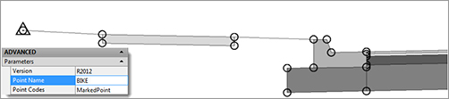
When using a marked point, name it right away, and make note of that name for using it with its “friends” (Figure 8-48).
Figure 8-48: Name the marked point in the Advanced Parameters.
Linking to a Marked Point
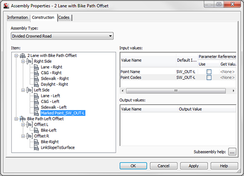
In the example shown in Figure 8-49, a LinkToMarkedPoint2 subassembly is placed on the right side of the bike path pavement. The LinkToMarkedPoint2 subassembly has been created to look for the marked point on the left side of the sidewalk buffer.
Figure 8-49: Add the name of the marked point before you place it on the assembly.

In the Advanced Parameters of the subassembly, place the name of the marked point. Add the name of the marked point before you place it on the assembly. Be sure to tell your subassembly the name of the marked point before you place it on your assembly.
At this stage, the geometry for a subassembly using a marked point is not known. The final geometry will be determined when you plug it into a corridor. All subassemblies that use the marked point will appear with the “Layout Mode” placeholder. Subassemblies designed to look for a marked point include:
- LinkToMarkedPoint
- LinkToMarkedPoint2
- LinkSlopesBetweenPoints
- MedianRaisedWithCrown
- MedianRaisedConstantSlope
- MedianDepressed
- Channel
- ChannelParabolicBottom
- OverlayParabolic
- UrbanReplaceCurbGutter (1 and 2)
Making Sure Your Marked Point Processes
Always place the marked point before the links that use it to avoid having to reorder subassemblies in the Construction tab of Assembly Properties. If the marked point is listed below the subassembly that needs it in the Construction tab, Civil 3D will not process it.
To reorder subassemblies in this dialog, right-click the subassembly and select Move Up or Move Down as needed.