
Beyond the simple nature of lines and arcs, alignments represent other things such as highways, streams, sidewalks, or even flight patterns. All these items have properties that help define them, and many of these properties can also be part of your alignments. In addition to obvious properties like names and descriptions, you can include functionality such as superelevation, station equations, reference points, and station control. This section will look at other properties that can be associated with an alignment and how to edit them.
Renaming Objects
The default naming convention for alignments is flexible (and configurable) but not descriptive. In previous sections, you ignored the descriptions and left the default names in place, but now let’s modify them. In addition, you’ll learn the easy way to change the object style and how to add a description.
Most of an alignment’s basic properties can be modified in Prospector. In this exercise, you’ll change the name in a couple of ways:
1. Open the AlignmentProperties.dwg file, and make sure Prospector is open.
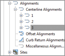
2. Expand the Alignments/Centerline Alignments collection, and note that Alignment – (1) through Alignment – (3) are listed as members.
3. Click the Centerline Alignments branch, and the individual alignments appear in a preview area (see Figure 6-38).
Figure 6-38: The Alignments collection listed in the preview area of Prospector
4. Down in the grid view section, click in the Name field for Alignment – (3), and pause briefly before clicking again. The text highlights for editing.
5. Change the name to Cabernet Court, and press ↵. The field updates, as does Prospector.
6. Click in the Description field, and enter a description. Press ↵.
7. Click the Style field, and the Select Label Style dialog appears. Select Layout from the drop-down menu, and click OK to dismiss. The screen updates.
That’s one method. The next is to use the AutoCAD Object Properties Manager (OPM) palette:
1. Open the OPM palette by using the Ctrl+1 keyboard shortcut or some other method.
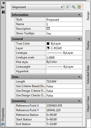
2. Select Alignment – (1) in the drawing (the horizontal alignment). The OPM looks like Figure 6-39.
Figure 6-39: Alignment – (1) in the AutoCAD Object Properties Manager palette
3. Click in the Name field, and change the name to Syrah Way.
4. Click in the Description field, and enter a description. Click OK.
5. Press Esc on your keyboard to deselect all objects, and close the OPM dialog if you’d like.
The final method involves getting into the Alignment Properties dialog, your access point to information beyond the basics:
1. In the main Prospector window, right-click Alignment – (2), and select Properties. This is the alignment at the top. The Alignment Properties dialog for Alignment – (2) opens.
2. Change to the Information tab if it isn’t selected.
3. Change the name to Frontenac Drive, and enter a description in the Description field.
4. Set Object Style to Existing.
5. Click Apply. Notice that the dialog header updates immediately, as does the display style in the drawing.
6. Click OK to exit the dialog.
Now that you’ve updated your alignments, let’s make them all the same style for ease of viewing. The best way to do this is in the Prospector preview window:
1. Pick the Alignments Centerline Alignments branch, and highlight one of the alignments in the preview area.
2. Press Ctrl+A to select them all, or pick the top and then Shift+click the bottom item. The idea is to pick all of the alignments.
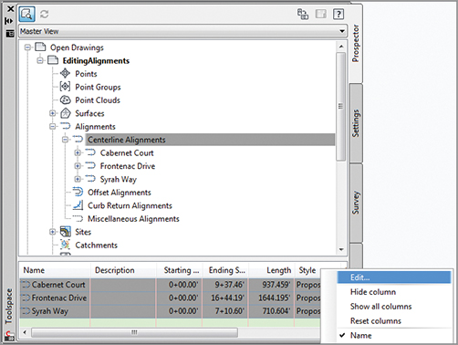
3. Right-click the Style column header and select Edit (see Figure 6-40).
Figure 6-40: Editing alignment styles en masse via Prospector
4. Select Layout from the drop-down list in the Select Label Style dialog that appears, and click OK. Notice that all alignments pick up this style. Although the dialog is named Edit Label Style, you are editing the object style.
Don’t Forget This Technique
This technique works on every object that displays in the List Style preview: parcels, pipes, corridors, assemblies, and so on. It can be painfully tedious to change a large number of objects from one style to another using any other method.
The alignments now look the same, and they all have a name and description. Let’s look beyond these basics at the other properties you can modify and update.
The Right Station
At the end of the process, every alignment has stationing applied to help locate design information. This stationing often starts at zero, but it can also tie to an existing object and may start at some arbitrary value. Stationing can also be fixed in both directions, requiring station equations that help translate between two disparate points that are the basis for the stationing in the drawing.
One common problem is an alignment that was drawn in the wrong direction. Thankfully, Civil 3D has a quick edit command to fix that:
1. Open the AlignmentProperties.dwg file, and make sure Prospector is open.
2. Pick Syrah Way and choose Reverse Direction from the Modify drop-down panel.
3. A warning message appears, reminding you of the consequences of such a change. Click OK to dismiss it.
4. The stationing reverses, with 0+00 now at the west end of the street.
This technique allows you to reverse an alignment almost instantly. The warning that appears is critical, though! When an alignment is reversed, the information that was derived from its original direction may not translate correctly, if at all. One prime example of this is design profiles: they don’t reverse themselves when the alignment is reversed, and this can lead to serious design issues if you aren’t paying attention.
Beyond reversing, it’s common for alignments to not start with zero. For example, the Cabernet Court alignment may be a continuation of an existing street, and it makes sense to make the starting station for this alignment the end station from the existing street. In this exercise, you’ll set the beginning station:
1. Select the Cabernet Court alignment.
2. Select Alignment Properties from the Modify panel.
3. Switch to the Station Control tab. This tab controls the base stationing and lets you create station equations.
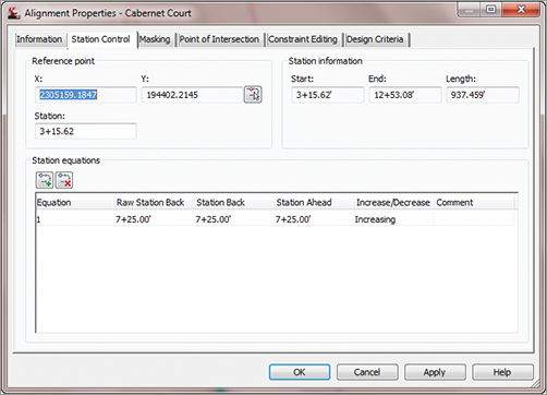
4. Enter 315.62 in the Station field in the Reference Point section (see Figure 6-41), and click Apply.
Figure 6-41: Setting a new starting station on the Cabernet Court alignment

5. Dismiss the warning message that appears, and click Apply again. The Station Information section in the top right updates. These options can’t be edited but provide a convenient way for you to review the alignment’s length and station values.
In addition to changing the value for the start of the alignment, you could use the Pick Reference Point button, as shown earlier in Figure 6-41, to select another point as the stationing reference point.
Station equations can occur multiple times along an alignment. They typically come into play when plans must match existing conditions or when the stationing has to match other plans, but the lengths in the new alignment would make that impossible without some translation. In this exercise, you’ll add a station equation about halfway down Cabernet Court for illustrative purposes:
1. On the Station Control tab of the Alignment Properties dialog, click the Add Station Equations button.
2. Change the Station value to 725. (Again, you’re going for illustration, not reality!)
3. Click Apply, and notice the change in the Station Information section (see Figure 6-42).
Figure 6-42: Cabernet Court station equation in place
Click OK to close the dialog, and review the stationing that has been applied to the alignment.
Stationing constantly changes as alignments are modified during the initial stages of a development or as late design changes are pushed back into the plans. With the flexibility shown here, you can reduce the time you spend dealing with minor changes that seem to ripple across an entire plan set.
Assigning Design Speeds
One driving part of transportation design is the design speed. Civil 3D considers the design speed a property of the alignment, which can be used in labels or calculations as needed. In this exercise, you’ll add a series of design speeds to Frontenac Drive. Later in the chapter, you’ll label these sections of the road:
1. Bring up the Alignment Properties dialog for Frontenac Drive to the north using any of the methods discussed.
2. Switch to the Design Criteria tab.
3. Click in the Design Speed field for Number 1, and enter 30. This speed is typical for a subdivision street.
4. Click the Add Design Speed button.
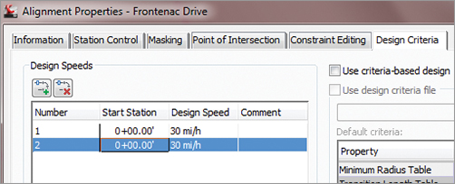
5. Click in the Start Station field for Number 2. A small Pick On Screen button appears to the right of the Start Station value, as shown in Figure 6-43.
Figure 6-43: Setting the design speed for a Start Station field
6. Click the Pick On Screen button, and then use a snap to pick the PC on the southwest portion of the site, near station 2 + 25.
7. Enter a value of 20 in the Design Speed field for Number 2.
8. Click the Pick On Screen button again to add one more design speed portion, and either pick or enter 9+00 to select the end of the tangent.
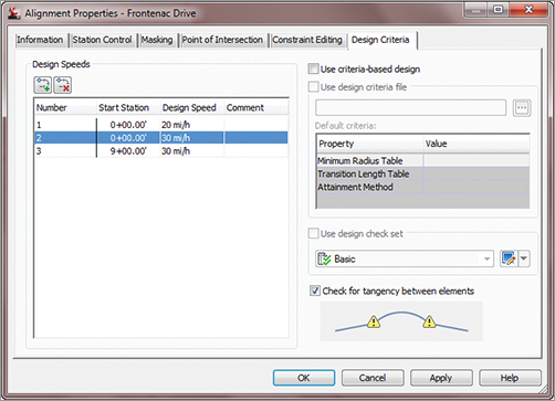
9. Enter a value of 30 for this design speed. When complete, the tab should look like Figure 6-44.
Figure 6-44: The design speeds assigned to Frontenac Drive
In a subdivision, these values can be inserted for labeling purposes. In a highway design, they can be used to drive the superelevation calculations that are critical to a working design. Chapter 11, “Superelevations,” looks at this subject.
Labeling Alignments
Labeling in Civil 3D is one of the program’s strengths, but it’s also an easy place to get lost. There are myriad options for every type of labeling situation under the sun, and keeping them straight can be difficult. In this section, you’ll begin by building label styles for stationing along an alignment, culminating in a label set. Then, you’ll create styles for station and offset labels, using reference text to describe alignment intersections. Finally, you’ll add a street-name label that makes it easier to keep track of things.
The Power of Label Sets
When you think about it, any number of items can be labeled on an alignment, before getting into any of the adjoining objects. These include major and minor stations, geometry points, design speeds, and profile information. Each of these objects can have its own style. Keeping track of all these individual labeling styles and options would be burdensome and uniformity would be difficult, so Civil 3D features the concept of label sets.
A label set lets you build up the labeling options for an alignment, picking styles for the labels of interest, or even multiple labels on a point of interest, and then save them as a set. These sets are available during the creation and labeling process, making the application of individual labels less tedious. Out of the box, a number of sets are available, primarily designed for combinations of major and minor station styles along with geometry information.
You’ll learn how to create individual label styles in Chapter 19. We will use the out-of-the-box styles over the next couple of exercises and then pull them together with a label set. At the end of this section, you’ll apply your new label set to the alignments.
Major Station
Major station labels typically include a tick mark and a station callout.
Geometry Points
Geometry points reflect the PC, PT, and other points along the alignment that define the geometric properties. The existing label style doesn’t reflect a plan-readable format, so you’ll copy it and make a minor change in this exercise.
In this exercise, you’ll apply a label set to all of your alignments and then see how an individual label can be changed from the set:
1. Open the AlignmentLabels.dwg file.
2. Select the Cabernet Court alignment on the screen. Cabernet Court is the southern alignment.
3. Right-click, and select Edit Alignment Labels to display the Alignment Labels dialog shown in Figure 6-45.
Figure 6-45: The Alignment Labels dialog for Cabernet Court

4. Click the Import Label Set button near the bottom of this dialog.
5. In the Select Style Set drop-down list, select the Paving Label Set and click OK.
6. The Style field for the alignment labels populates with the option you selected.
7. Click OK to dismiss the dialog.
8. Repeat this process across the rest of the alignments.
9. When you’ve finished, zoom in on any of the major station labels.
10. Hold down the Ctrl key, and select the label. Notice that a single label is selected, not the label set group.
11. Right-click and select Label Properties.
12. The Label Properties dialog appears; click another label style from the drop-down list.
13. Change the Major Station Label Style value to Parallel with Tick, and change the Flip Label value to True.
14. Press Esc to deselect the label item and exit this dialog.
By using alignment label sets, you’ll find it easy to standardize the appearance of labeling and stationing across alignments. Building label sets can take some time, but it’s one of the easiest, most effective ways to enforce standards.
Ctrl+Click? What Is That About?
Prior to AutoCAD Civil 3D 2008, clicking an individual label picked the label and the alignment. Because labels are part of a label set object now, Ctrl+click is the only way to access the Flip Label and Reverse Label functions!
Station Offset Labeling
Beyond labeling an alignment’s basic stationing and geometry points, you may want to label points of interest in reference to the alignment. Station offset labeling is designed to do just that. In addition to labeling the alignment’s properties, you can include references to other object types in your station offset labels. The objects available for referencing are as follows:
- Alignments
- COGO points
- Parcels
- Profiles
- Surfaces
In this exercise, you’ll use an alignment reference to create a label suitable for labeling the intersection of two alignments. It will pick up the stationing information from both:
1. Go to the Annotate tab of the Ribbon. From the Add Labels drop-down, select Alignment Add Alignment Labels. The Add Labels dialog appears.
2. In the Label Type drop-down list, select Station Offset.
3. In the Station Offset Label Style drop-down, select Alignment Intersection.
4. Leave the Marker Style field alone, but remember that you could use any of these styles to mark the selected point.
5. Click the Add button.
6. Pick the Syrah Way alignment.
7. Snap to the intersection of Syrah Way and Frontenac Drive. It is the one on the right.
8. Enter 0 for the offset amount, and press ↵.
9. The command line prompts you to Select Alignment for Label Style Component Intersecting Alignment. Pick the Frontenac Drive alignment.
10. Click the Add button again, and repeat the process at the other two alignment intersections.
There are two things to note in this process: first, you click Add between adding labels because Civil 3D otherwise assumes you want to use the same reference object for every instance of the label; second, the labels are sitting right on the point of interest. Drag them to a convenient location, and you’re set to go. When you do this, your label should look something like the one shown in Figure 6-46.
Figure 6-46: The Alignment Intersection label style in use

Using station offset labels and their reference object ability, you can label most site plans quickly with information that dynamically updates. Because of the flexibility of labels in terms of style, you can create “design labels” that are used to aid in modeling yet never plot and aren’t seen in the final deliverables. This is ideal in corridor modeling, as discussed in Chapter 10, “Advanced Corridors, Intersections, and Roundabouts.”
Segment Labeling
Every land development professional has a story about the developer who named an entire subdivision after their kids, grandkids, dogs, golf buddies, favorite bars, and so on. As these plans work their way through reviewing agencies, there are inevitably changes, and the tedium of changing a street name on 45 pages of construction documents can’t be described.
Thankfully, as you’ve already seen in the station offset label, you can access the properties of the alignment to generate a label. In this exercise, you’ll use that same set of properties to create street-name labels that are applied and always up-to-date:
1. Open the AlignmentSegments.dwg file.
2. Change to the Annotate tab and choose the Add Labels button on the Labels & Tables panel to display the Add Labels dialog shown in Figure 6-47.
Figure 6-47: The Add Labels dialog

3. In the Label Type field, select Single Segment from the drop-down. Then, in the Line Label Style field, select the Street Names style. Note that curves and spirals have their own set of styles. If you click a curve during the labeling process, you won’t get a street name—you’ll get something else.
4. Click the Add button.
5. Pick various line segments around the drawing. Each street is labeled with the appropriate name. You may need to flip the label so that it does not interfere with the station labels.
6. Click the Close button to close the Add Labels dialog.
Days of work averted! The object properties of an alignment can be invaluable in documenting your design. Creating a collection of styles for all the various components and types takes time but pays you back in hours of work saved on every job.
Alignment Tables
There isn’t always room to label alignment objects directly on top of them. Sometimes doing so doesn’t make sense, or a reviewing agency wants to see a table showing the radius of every curve in the design. Documentation requirements are endlessly amazing in their disparity and seeming randomness. Beyond labels that can be applied directly to alignment objects, you can also create tables to meet your requirements and get plans out the door.
You can create four types of tables:
- Lines
- Curves
- Spirals
- Segments
Each of these is self-explanatory except perhaps the Segments table. That table generates a mix of all the lines, curves, and spirals that make up an alignment, essentially re-creating the alignment in a tabular format. In this section, you’ll generate a new line table and draw the segment table that ships with the product.
All the tables work in a similar fashion. Go to the Annotate tab of the Ribbon. From the Add Tables drop-down, select Alignment, and then pick a table type that is relevant to your work. The Table Creation dialog appears (see Figure 6-48).
Figure 6-48: The Table Creation dialog

You can select a table style from the drop-down list or create a new one. Select a table layer by clicking the blue arrow. The selection area determines how the table is populated. All the label-style names for the selected type of component are presented, with a check box to the right of each one. Applying one of these styles enables the Selection Rule, which has the following two options:
Add Existing Any label using this style that currently exists in the drawing is converted to a tag format, substituting a key number such as L1 or C27, and added to the table. Any labels using this style created in the future will not be added to the table.
Add Existing and New Any label using this style that currently exists in the drawing is converted to a tag format and added to the table. In addition, any labels using this style created in the future will be added to the table.
To the right of the Select section is the Split Table section, which determines how the table is stacked up in model space once it’s populated. You can modify these values after a table is generated, so it’s often easier to leave them alone during the creation process.
Finally, the Behavior section provides two selections for the Reactivity Mode: Static and Dynamic. These selections determine how the table reacts to changes in the driving geometry. In some cases in surveying, this disconnect is used as a safeguard to the platted data, but in general, the point of a 3D model is to have live labels that dynamically react to changes in the object.
Before you draw any tables, you need to apply labels so the tables will have data to populate. In this exercise, you’ll throw some labels on your alignments, and then you’ll move on to drawing tables in the next sections:
1. Open the AlignmentSegments.dwg file.
2. Change to the Annotate tab and choose Add Labels from the Labels & Tables panel to open the Add Labels dialog.
3. In the Feature field, select Alignment, and then in the Label Type field, select Multiple Segment from the drop-down list. With this option, you’ll click each alignment one time, and every subcomponent will be labeled with the style selected here.
4. Verify that the Line Label Style field (not the General Line Label Style) is set to Bearing Over Distance. You won’t be left with these labels—you just want them for selecting elements later.
5. Click Add, and select all three alignments.
6. Click Close to close the Add Labels dialog.
Now that you’ve got labels to play with, let’s build some tables.
Creating a Line Table
Most line tables are simple: a line tag, a bearing, and a distance. You’ll also see how Civil 3D can translate units without having to change anything at the drawing level:
1. Choose the Add Tables drop-down arrow from the Labels & Tables panel, and choose Alignment Add Line to open the Table Creation dialog.
2. Set the dialog options as shown in Figure 6-49, and click OK.
Figure 6-49: Creating a line table

3. Pick a point on screen, and the table will generate.
Pan back to your drawing, and you’ll notice that the line labels have turned into tags on the line segments. After you’ve made one table, the rest are similar. Be patient as you create tables—a lot of values must be tweaked to make them look just right. By drawing one on screen and then editing the style, you can quickly achieve the results you’re after.
An Alignment Segment Table
An individual segment table allows a reviewer to see all the components of an alignment. In this exercise, you’ll draw the segment table for Frontenac Drive:
1. Choose the Add Tables drop-down arrow from the Labels & Tables panel, and choose Alignment Add Segment to open the Table Creation dialog.
2. In the Select Alignment field, choose the Frontenac Drive alignment from the drop-down list, and click OK.
3. Pick a point on the screen, and the table will be drawn.