Once a basic surface is built, and, in some cases, even before it is built, you can do some cleanup and modification to the TIN construction that make it much more usable and realistic. Some of these edits include limiting the input data, tweaking the triangulation, adding in breakline information, or hiding areas from view. In this section, we explore a number of ways of refining surfaces to end up with the best possible model from which to build.
Surface Properties
The most basic steps you can perform in making a better model are right in the Surface Properties dialog. The surface object contains information about the build and edit operations, along with some values used in surface calculations. These values can be used to tweak your surface to a semi-acceptable state before more manual operations are needed.
In this exercise, you’ll go through a couple of the basic surface-building controls that are available. You’ll do them one at a time in order to measure their effects on the final surface display.
1. Open the SurfaceProperties.dwg file. This is the Points From Text drawing that you worked on earlier but has the polylines frozen.
2. Expand the Surfaces branch.
3. Right-click EG and select Surface Properties. The Surface Properties dialog appears.
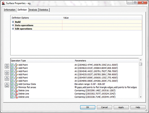
4. Select the Definition tab. Note the list at the bottom of the dialog.
5. Under the Definition Options at the top of the dialog, expand the Build option.
The Build options of the Definition tab allow you to tweak the way the triangulation occurs. The basic options are listed here:
Copy Deleted Dependent Objects When you select Yes and an object that is part of the surface definition (such as the polylines you used in your aerial surface, for instance) is deleted, the information derived from that object is copied into the surface definition. Setting this option to True in the EG Surface properties will let you erase the polylines from the drawing file while still maintaining the surface information.
Exclude Elevations Less Than Setting this to Yes puts a floor on the surface. Any point that would be built into the surface but that is lower than the floor is ignored. In the EG surface, there are calculated boundary points with zero elevations, causing real problems that can be solved with this simple click. The floor elevation is controlled by the user.
Exclude Elevations Greater Than The idea is the same as with the preceding option, but a ceiling value is used.
Use Maximum Triangle Length This setting attempts to limit the number of narrow “sliver” triangles that typically border a site. By not drawing any triangle with a length greater than the user input value, you can greatly refine the TIN.
Convert Proximity Breaklines To Standard Toggling this to Yes will create breaklines out of the lines and entities used as proximity breaklines. We’ll look at this more later.
Allow Crossing Breaklines This option determines what Civil 3D should do if two breaklines in a surface definition cross each other. An (x,y) coordinate pair cannot have two z values, so some decision must be made about crossing breaklines. If you set this to Yes, you can then select whether to use the elevation from the first or the second breakline or to average these elevations.
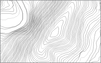
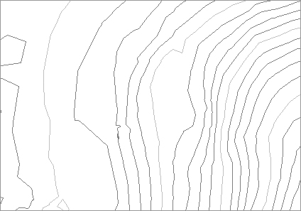
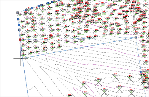
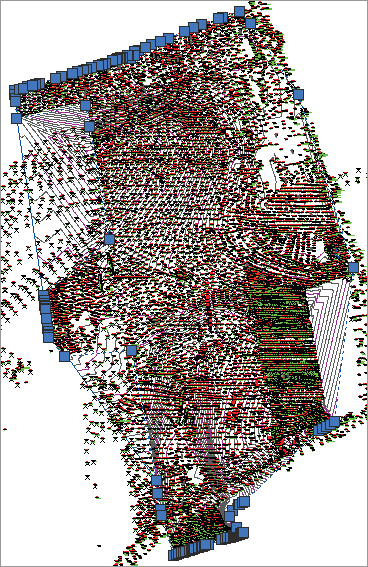
If you look at the surface, you might not notice a blob area as shown in the top panel of Figure 4-16. When you zoom in closer to inspect the surface, it appears that there are a series of blown shots, causing the elevation to dip to zero, as shown in the bottom panel of Figure 4-16. In this next portion of the exercise, you’ll limit the build options to make that blown surface “disappear”:
Figure 4-16: Overall EG surface (top). EG Surface showing blown points (bottom).

1. Set the Exclude Elevations Less Than value to Yes.
2. Set the Value to 200 and click OK to exit the dialog. Elevations less than 200″ will be excluded.
3. A warning message will appear. Civil 3D is simply warning you that your surface definition has changed. Click Rebuild The Surface to rebuild the surface. When it’s done, it should look like Figure 4-17.
Figure 4-17: EG surface after ignoring low elevations
Although this surface is better than the original, there are still huge areas being contoured that probably shouldn’t be. By changing the style to review the surface, you can see where you still have some issues:
1. Open the Surface Properties dialog again, and switch to the Information tab.
2. Change the Surface Style field to Contours And Triangles.
3. Click Apply. Doing so makes the changes without exiting the dialog.
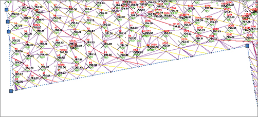
4. Drag the dialog to the side so you can see the site. On the outer edges of the site, you can see some long triangles formed in areas where there was no survey taken but the surface decided to connect the triangles anyway (Figure 4-18, left).
Figure 4-18: EG surface before Maximum Triangle (left) and after (right)

5. Switch to the Definition tab.
6. Expand the Build option.
7. Set the Use Maximum Triangle Length value to Yes.
8. In the Maximum Triangle Length value field, type 300″.
9. Click OK to apply and exit the dialog.
10. Click Rebuild The Surface to update and dismiss the warning message to see the revised surface (Figure 4-18, right).
The value is a bit high, but it is a good practice to start with a high value and work down to avoid losing any pertinent data. Setting this value to 225″ will result in a surface that is acceptable because it doesn’t lose a lot of important points. Beyond this, you’ll need to look at making some edits to the definition itself instead of modifying the build options.
Surface Additions
Beyond the simple changes to the way the surface is built, you can look at modifying the pieces that make up the surface. With your drawing so far, you have merely been building from points. Although this is OK for small surfaces, you need to go further with this surface. In this section, you’ll add a few breaklines and a border and finally perform some manual edits to your site.
You Can’t Always Get What You Want
But sometimes you get what you need. Autodesk has included the ability to reorder the build operations on the Surface Definition tab. If you look at the lower left of the Surface Properties Definition tab shown here, you’ll find that there are arrows to the left of the list box showing all the data, edits, and changes you’ve made to the surface.
As Civil 3D builds a surface, it processes this data and information from top to bottom—in this case, adding points, and then the breaklines, and then a boundary, and so on. If a later operation modifies one of these additions or edits, the later operation takes priority. To change the processing order, select an operation, and then use the arrows at the left to push it up or down within the process. One common example of this is to place a boundary as the last operation to ensure accurate triangulation. You’ll look at boundaries in the next section.
Adding Breakline Information
Breaklines can come from any number of sources. They can be approximated on the basis of aerial photos of the site that help define surface features, or they can be directly input from field book files and the Civil 3D survey functionality. Five types of breaklines are available for use:
Standard Breaklines Built on the basis of 3D lines, feature lines, or polylines, standard breaklines typically connect points already included but can contain their own elevation data. Simple-use cases for connecting the dots include linework from a survey or drawing a building pad to ensure that a flat area is included in the surface. Feature lines and 3D polylines are often used as the mechanism for grading design and include their own vertical information. An example might be the description of a parking lot area or a drainage swale behind a building.
Proximity Breaklines These breaklines allow you to force triangulation without picking precise points. They will not add vertical information to the surface.
Wall Breaklines Wall breaklines define walls in surfaces. Because of the limitation of true vertical surfaces, a wall breakline will let you approximate a wall without having to create an offset. They are defined on the basis of an elevation at a vertex, and then an elevation difference at each vertex.
From File You can select this option if a text file contains breakline information. This file can be the output of another program and can be used to modify the surface without creating additional drawing objects.
Nondestructive Breaklines This type of breakline is designed to maintain the integrity of the original surface while updating triangulation.
In most cases, you’ll build your surfaces from standard, proximity, and wall breaklines. In this example, you’ll add in some breaklines that describe road and surface features:
1. Open the SurfaceBreaklines.dwg file. This drawing has been modified and stylized per company standards. For more information on styles, see Chapter 19, “Styles.”
2. Thaw the _Polylines-Road layer, if necessary. The roads are the color red.
3. Right-click on one of the red polylines and select Similar. All the red polylines are now highlighted.
4. In Prospector, expand the Surfaces EG Definition branches.
5. Right-click Breaklines and select the Add option. The Add Breaklines dialog appears.
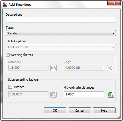
6. Enter a description if you wish and the settings as shown in Figure 4-19. Click OK to accept the settings and close the dialog Dismiss Panorama.
Figure 4-19: The Add Breaklines dialog
7. If necessary, thaw the _Polylines-Surface layer. The Surface polylines are the color green.
8. Repeat steps 3–5 but change the description to Surface Polylines Dismiss Panorama.
9. Press ↵ to complete the command.
The surface changes reflect the breaklines added. You can see that the original border has expanded to include the breakline data. We want to clean that up so we will rectify that problem with the next exercise. On sites with more extreme grade breaks, such as those that might follow a channel or a site grading, breaklines are invaluable in building the correct surface.
Crossing Breaklines
Invariably, you will see Panorama pop up with a message about crossing breaklines. In general, Civil 3D does not like breaklines that cross themselves.
The Resolve Crossing Breaklines tool will let you examine those situations.
1. Click on the surface.
2. From the Tin Surface tab and Analyze panel, select the Resolve Crossing Breaklines tool.
3. At the Please specify the types of breakline you want to find or [surveyDatabase/Figure/Surface]: prompt, type S↵ to select the surface option.
4. The Crossing Breaklines tab on Panorama shows you the crossing breaklines and you can decide how you want to resolve them using Use Higher Elevation, Use Lower Elevation, Use Average Elevation, or Use Specified Elevation, as shown below. As you click on each breakline and press resolve, it disappears from the conflict list.
Adding a Surface Border
In the previous exercise, you fixed some breakline issues. However, in the data presented, the bigger issue is still the number of inappropriate triangles that are being drawn along the edge of the site. It is often a good idea to leave these triangles untouched during the initial build of a surface, because they serve as pointers to topographical data (such as monumentation, control, utility information, and so on) that may otherwise go unnoticed without a visit to the site. This is a common problem that can be solved by using a surface border. You can sketch in a polyline to approximate a border, but the Extract Objects From Surface utility gives you the ability to use the surface itself as a starting point.
The Extract Objects From Surface utility allows you to re-create any displayed surface element as an independent AutoCAD entity. This entity can be the contours, grid, 3D faces, and so forth. In this exercise, you’ll extract the existing surface boundary as a starting point for creating a more refined boundary that will limit triangulation:
1. Open the SurfacePoints.dwg file.
2. Select Extents from the Navigate panel on the View tab to view the whole surface on screen.
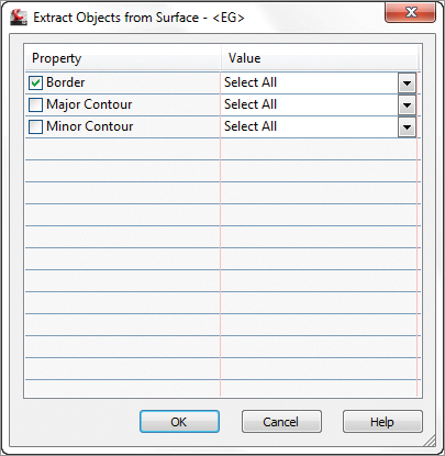
3. Select the surface and click Extract Objects on the Surface Tools panel to open the Extract Objects From Surface dialog.
4. Deselect the Major Contour and Minor Contour options, as shown in Figure 4-20.
Figure 4-20: Extracting the border from the surface object
5. Click OK to finish the process. Press Esc to deselect the surface.
6. Pick the blue border line, and notice from the grips displayed that you are no longer selecting the surface but a 3D polyline.
This polyline will form the basis for your final surface boundary. By extracting the polyline from the existing surface, you save a lot of time playing connect the dots along the points that are valid. Next, you’ll refine this polyline and add it to the surface as a boundary.
7. In Prospector, right-click Point Groups and select the Properties option. The Point Groups dialog appears.
8. Move _All Points to the top of the list using the up and down arrows on the right.
9. Click OK to display all of your points on the screen.
10. Working your way around the site, grip-edit the polyline you created in step 6 to include some of the roadway. On a large site, you can see that this is a time-consuming process but worth the effort to clean up the site nicely (Figure 4-21). When complete, your polyline might look something like Figure 4-22.
Figure 4-21: Using the grips to adjust the border
Just as with breaklines, there are multiple types of surface boundaries:
Outer Boundaries Use this type to define the outer edge of the shown boundary. When the Non-destructive Breakline option is used, the points outside the boundary are still included in the calculations; then additional points are created along the boundary line where it intersects with the triangles it crosses. This boundary trims the surface for display but does not exclude the points outside the boundary. You’ll want to have your outer boundary among the last operations in your surface-building process.
Hide Boundaries Use this type to punch a hole in the surface display for tasks like building footprints or a wetlands area that are not to be touched by design. Hidden surface areas are not deleted but merely not displayed.
Figure 4-22: Revised surface border polyline
Show Boundaries Use this type to show the surface inside a hide boundary, essentially creating a donut effect in the surface display.
Data Clip Boundaries Data clip boundaries place limits on data that will be considered part of the surface from that point going forward. This type is different from an outer boundary in that the data clip boundary will keep the data from ever being built into the surface as opposed to limiting it after the build. Using data clip boundaries is handy when you are attempting to build Civil 3D surfaces from large data sources such as Light Detection and Ranging (LIDAR) or DEM files. Because they limit data being placed into the surface definition, you’ll want to have data clips among the first operations in your surface.
The addition of every boundary is considered a separate part of the building operations. This means that the order in which the boundaries are applied controls their final appearance. For example, a show boundary selected before a hide boundary will be overridden by that hide operation. To finish the exercise, you’ll add the outer boundary twice, once as a nondestructive breakline and once with a standard breakline, and observe the difference.
1. In Prospector, expand the Surfaces branch.
2. Right-click EG and select the Surface Properties option. The Surface Properties dialog appears.
3. Change Surface Style to 1″ and 5″ TIN Editing (Ex.).
4. In Prospector, expand the Surfaces EG Definition branches.
5. Right-click Boundaries and select the Add option. The Add Boundaries dialog opens.
6. Enter a name if you like and check the Non-destructive Breakline option.
7. Pick the polyline and notice the immediate change.
8. Zoom in on the northwest portion of your site, as shown in Figure 4-23.
Figure 4-23: A nondestructive border in action
Notice how the triangulation appears to include lines to nowhere. This is the nature of the nondestructive breakline. The points you attempted to exclude from the surface are still being included in the calculation; they are just excluded from the display. This isn’t the result you were after, so let’s fix it now:
1. In Prospector, expand the Surfaces EG Definition branches and select Boundaries.
2. A listing of the boundaries appears in the preview area.
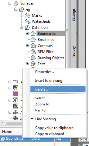
3. Right-click the border you just created and select Delete, as shown in Figure 4-24. Click OK in the warning dialog that tells you the selected definition items will be permanently removed from the surface.
Figure 4-24: Deleting a surface boundary
4. In Prospector, expand the Surfaces branch and right-click EG. Select the Rebuild option to return to the prior version of the surface.
5. Right-click Boundaries and select the Add option again. The Add Boundaries dialog appears.
6. This time, leave the Non-destructive Breakline option deselected and click OK.
7. Pick the border polyline on your screen. Notice that no triangles intersect your boundary now where it does not connect points.
8. On the main menu, choose View Zoom Extents to see the result of the border addition.
In spite of adding breaklines and a border, you still have some areas that need further correction or changes.
Surface Cropping
Surface cropping is useful when working with a small portion of a much larger surface. A cropped area within a surface becomes a separate surface object (a new surface) to be managed and manipulated on a much smaller scale. In this example, you will create a cropped surface and add it to an existing drawing:
1. Open the SurfaceCrop.dwg file.
2. Select the surface and expand the Surface Tools drop-down panel on the Tin Surface: EG tab. Select Create Cropped Surface. The Create Cropped Surface dialog is displayed, as shown in Figure 4-25.
Figure 4-25: The Create Cropped Surface dialog
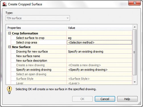
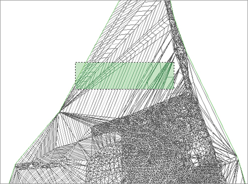
3. Select the ellipsis next to Select Crop Area and type O↵. Object is now displayed in the Select Crop Area Value. Select the red rectangle on the surface and press ↵.
4. Select the rectangle when prompted for a point. The rectangle is now highlighted.
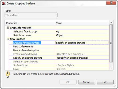
5. For Drawing For New Surface, select Create A New Drawing from the drop-down, as shown in Figure 4-26.
Figure 4-26: New surface selection
6. In the Value column for New Surface Name, enter Cropped Area. You can also type a description for the new surface if desired.
7. Click the ellipsis next to Create A New Drawing. The Select Template dialog opens. Select a template and click Open.
8. The Value column for Create A New Drawing is populated with the next open drawing name, such as Drawing2.dwg.
9. You can select a surface style and a layer for the surface to be created on. Your dialog should look like Figure 4-27.
Figure 4-27: The completed Create Cropped Surface dialog

10. Click OK to complete the command and create a cropped surface in the existing drawing.
11. Open the drawing Surface Cropping - Final.dwg to reveal this new surface, as shown in Figure 4-27.
Rendering with Materials?
A Civil 3D surface must display triangles for rendering materials to be calculated and shown. You will inevitably forget this; it’s just one of those frustrating anomalies in the program.
Manual Surface Edits
In your surface, you have a few “finger” surface areas where the surveyors went out along narrow paths from the main area of topographic data. The nature of TIN surfaces is to connect dots, and so these fingers often wind up as webbed areas of surface information that’s not accurate or pertinent. A number of manual edits can be performed on a surface. These edit options are part of the definition of the surface and include the following:
Add Line Connects two points where a triangle did not exist before. This option essentially adds a breakline to the surface, so adding a breakline would generally be a better solution.
Delete Line Removes the connection between two points. This option is used frequently to clean up the edge of a surface or to remove internal data where a surface should have no triangulation at all. This can be an area such as a building pad or water surface.
Swap Edge Changes the direction of the triangulation methodology. For any four points, there are two solutions to the internal triangulation, and the Swap Edge option alternates from one solution to the other.
Add Point Allows for the manual addition of surface data. This function is often used to add a peak to a digitized set of contours that might have a flat spot at the top of a hill or mountain.
Delete Point Allows for the manual removal of a data point from the surface definition. Generally, it’s better to fix the source of the bad data, but this option can be a fix if the original data is not editable (in the case of a LandXML file, for example).
Modify Point and Move Point Variations on the same idea. Modify Point moves a surface point in the z direction, whereas a Move Point is limited to horizontal movement. In both cases, only the TIN point is modified, not the original data input.
Minimize Flat Areas Performs the edits you saw earlier in this chapter to add supplemental information to the TIN and to create a more accurate surface, forcing triangulation to work in the z direction instead of creating flat planes.
Raise/Lower Surface A simple arithmetic operation that moves the surface in the z direction. This option is useful for testing rough grading schemes for balancing dirt or for adjusting entire surfaces after a new benchmark has been observed.
Smooth Surface Presents a pair of methods for supplementing the surface TIN data. Both work by extrapolating more information from the current TIN data, but they are distinctly different in their methodology:
Natural Neighbor Interpolation (NNI) Adds points to a surface on the basis of the weighted average of nearby points. This data generally works well to refine contouring that is sharply angular because of limited information or long TIN connections. NNI works only within the bounds of a surface; it cannot extend beyond the original data.
Kriging Adds points to a surface based on one of five distinct algorithms to predict the elevations at additional surface points. These algorithms create a trending for the surface beyond the known information and can therefore be used to extend a surface beyond even the available data. Kriging is very volatile, and you should understand the full methodology before applying this information to your surface. Kriging is frequently used in subsurface exploration industries such as mining, where surface (or strata) information is difficult to come by and the distance between points can be higher than desired.
Paste Surface Pulls in the TIN information from the selected surface and replaces the TIN information in the host surface with this new information. This option is helpful in creating composite surfaces that reflect both the original ground and the design intent. We’ll look at pasting in Chapter 16, “Plan and Production,” in the discussion on grading.
Simplify Surface Allows you to reduce the amount of TIN data being processed via one of two methods: Edge Contraction, wherein Civil 3D tries to collapse two points connected by a line to one point, or Point Removal, which removes selected surface points based on algorithms designed to reduce data points that are similar.
Manual editing should always be the last step in updating a surface. Fixing the surface is a poor substitution for fixing the underlying data the TIN is built from, but in some cases, it is the quickest and easiest way to make a more accurate surface.
Point and Triangle Editing
In this section, you’ll remove triangles manually, and then finish your surface by correcting what appears to be a blown survey shot.
1. Open the SurfaceEdits.dwg file.
2. In Prospector, expand the Surfaces EG Definition branches.
3. Right-click Edits and select the Delete Line option.
4. Enter C as the command line to enter a crossing selection mode.
5. Start at the lower right of the pick area shown in Figure 4-28, and move to the upper-left corner as shown. Right-click or press ↵ to finish the selection.
Figure 4-28: Crossing the window selection to delete TIN lines
6. Repeat this process, removing triangles until your site resembles Figure 4-29.
Figure 4-29: Surface after removal of extraneous triangles

7. Zoom to the portion of your site with the red circle, and you’ll notice a collection of contours that seems out of place.
8. Change Surface Style to Contours And Points.
9. Right-click Edits again and select the Delete Point option.
10. Zoom in on the area very close. You will find a series of red + markers in the area with close contours. These are blown shots and the contours are simply obeying the point elevation. In this case it is 0.
11. Delete the three markers, and notice the immediate change in the contouring.
Surface Smoothing
One common complaint about computer-generated contours is that they’re simply too precise. The level of calculations in setting elevations on the basis of linear interpolation along a triangle leg makes it possible for contour lines to be overly exact, ignoring contour line trends in place of small anomalies of point information. Under the eye of a board drafter, these small anomalies were averaged out, and contours were created with smooth flowing lines.
While you can apply object-level smoothing as part of the contouring process, this process smoothes the end result but not the underlying data. In this section, you’ll use the NNI smoothing algorithm to reduce surface anomalies and create a more visually pleasing contour set:
1. Open the SurfaceSmoothing.dwg file. The area to be smoothed is shown in Figure 4-30.
Figure 4-30: Area of surface to be smoothed

2. In Prospector, expand the Surfaces EG Definition branches.
3. Right-click Edits and select the Smooth Surface option. The Smooth Surface dialog opens.
4. Expand the Smoothing Methods branch, and verify that Natural Neighbor Interpolation is the Select Method value.
5. Expand the Point Interpolation/Extrapolation branch, and click in the Select Output Region value field. Click the ellipsis button.
6. Select the rectangle drawn on screen, and press ↵ to return to the Smooth Surface dialog.
7. Enter 20 for the Grid X-Spacing and Grid Y-Spacing values, and then press ↵. Note that Civil 3D will tell you how many points you are adding to the surface immediately below this input area by the value given in the Number Of Output Points field. It’s grayed out, but it does change on the basis of your input values.
8. Click OK and the surface will be smoothed, as shown in Figure 4-31.
Figure 4-31: Using NNI to smooth the surface

Note that we said the surface will be smoothed—not the contours. To see the difference, change Surface Style to Contours And Points to display your image as shown in Figure 4-32.
Figure 4-32: Points added via NNI surface smoothing

Note all of the points with a circle cross symbol. These points are all new, created by the NNI surface-smoothing operation. The points are part of your surface, and the contours reflect the updated surface information.
Surface Simplifying
Because of the increasing use in land development projects of GIS and other data-heavy inputs, it’s critical that Civil 3D users know how to simplify the surfaces produced from these sources. In this exercise, you’ll simplify the surface created from a drawing earlier in this chapter.
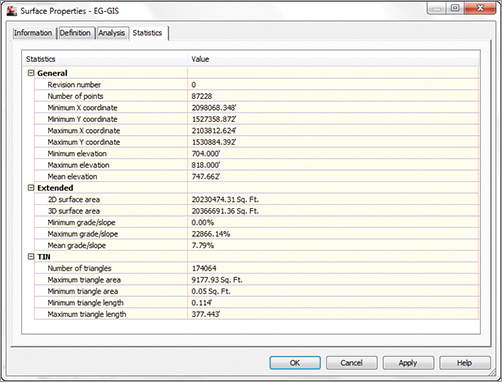
1. Open the SurfaceSimplifying.dwg file. For reference, the surface statistics for the EG-GIS surface are shown in Figure 4-33.
Figure 4-33: EG-GIS surface statistics before simplification
2. In Prospector, expand Surfaces EG-GIS Definition.
3. Right-click Edits and select Simplify Surface to launch the Simplify Surface wizard.
4. Select the Point Removal radio button, as shown in Figure 4-34, and click Next to move to the Region Options screen.
Figure 4-34: The Simplify Surface screen
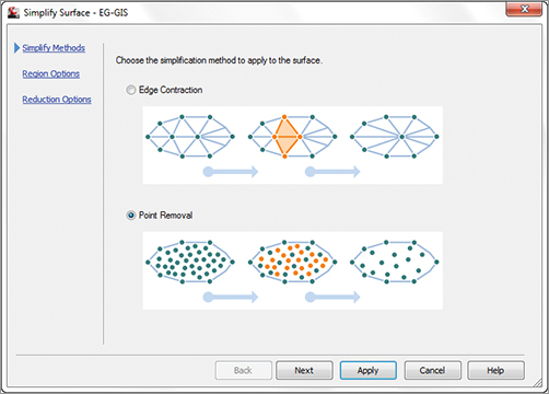
5. Leave the Region Option set to Use Existing Surface Border. There are also options for selecting areas with a window or polygon, as well as selecting based on an existing entity. Click Next to move to the Reduction Options screen.
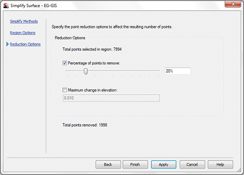
6. Set Percentage Of Points To Remove to 20 percent and then deselect the Maximum Change In Elevation option. This value is the maximum change allowed between the surface elevation at any point before or after the simplify process has run.
7. Click Apply. The program will process this calculation and display a Total Points Removed number, as shown in Figure 4-35. You can adjust the slider or toggle on the Maximum Change In Elevation button to experiment with different values.
Figure 4-35: Reduction Options screen in the Simplify Surface wizard
8. Click Finish to dismiss the wizard and fully commit to the Simplify edit.
A quick visit to the Surface Properties Statistics tab shows that the number of points has been reduced. On something like an aerial topography or DEM, reducing the point count probably will not reduce the usability of the surface, but this simple 10 percent point reduction actually takes almost 20 percent off the file size. Remember, you can always remove the edit or deselect the operation on the Definition tab of the Surface Properties dialog.
The creation of a surface is merely the starting point. Once you have a TIN to work with, you have a number of ways to view the data using analysis tools and varying styles. Styles will be covered in Chapter 19.
Level of Detail
When you have a surface such as the SurfaceSimplifying.dwg that you have just worked with, actual manipulation of the surface can get cumbersome due to the sheer volume of data that is there. This is further evidenced when you want to rotate the view.

Luckily, Civil 3D 2012 now has a new feature called Level of Detail. This can be found on the View tab and Views panel.

It is a toggle that is either on or off. When it is invoked, you will see your surface with fewer contours when you are zoomed out. However when you zoom in, the contours are back to normal. The figure on the left below shows the surface with the Level of Detail invoked while zoomed out, and the figure to the right shows the same surface with Level of Detail invoked and zoomed in.