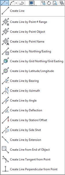
You can draw lines many ways in an AutoCAD-based environment. The tools found on the Draw panel of the Home tab create lines that are no more intelligent than those created by the standard AutoCAD Line command. How the Civil 3D lines differ from those created by the regular Line command isn’t in the resulting entity, but in the process of creating them. Figure 1-15 shows the available line commands.
Figure 1-15: Line creation tools
Note that you can switch between any of the Line commands without exiting the command. For example, if your first location is a point object, use Line By Point Object; then, without leaving the command, go back to the Lines/Curves menu and choose any Line or Curve command to continue creating your linework. You can also press the Esc key once, while in a Lines/Curves menu command, to resume the regular Line command.
Coordinate Line Commands
The next few commands discussed in this section help you create a line using Civil 3D points and/or coordinate inputs. Each command requires you to specify a Civil 3D point, a location in space, or a typed coordinate input. These Line tools are useful when your drawing includes Civil 3D points that will serve as a foundation for linework, such as the edge of pavement shots, wetlands lines, or any other points you’d like to connect with a line.
Line Command
The Create Line command on the Draw panel of the Home tab issues the standard AutoCAD Line command. It’s equivalent to typing line on the command line or clicking the Line tool on the Draw toolbar.
Create Line By Point # Range Command
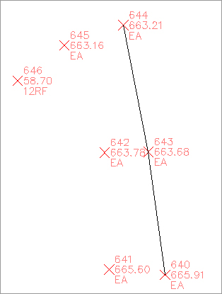
The Create Line By Point # Range command prompts you for a point number. You can type in an individual point number, press ↵, and then type in another point number. A line is drawn connecting those two points. You can also type in a range of points, such as 640-644. Civil 3D draws a line that connects those lines in numerical order—from 640 to 641, and so on (see Figure 1-16). This order won’t give you the desired linework for edge of asphalt, for example.
Figure 1-16: A line created using 640-644 as input
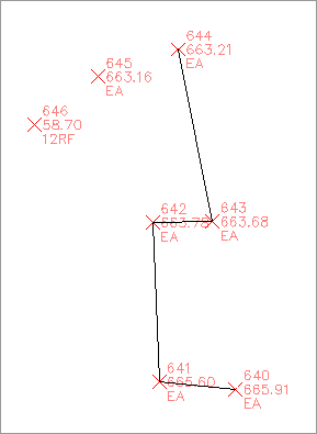
Alternatively, you can enter a list of points such as 640, 643, 644 (Figure 1-17). Civil 3D draws a line that connects the point numbers in the order of input. This approach is useful when your points were taken in a zigzag pattern (as is commonly the case when cross-sectioning pavement), or when your points appear so far apart in the AutoCAD display that they can’t be readily identified.
Figure 1-17: A line created using 640, 643, 644 as input
Create Line By Point Object Command
The Create Line By Point Object command prompts you to select a point object. To select a point object, locate the desired start point and click any part of the point. This tool is similar to using the regular Line command and a Node object snap (also known as osnap).
Create Line By Point Name Command
The Create Line By Point Name command prompts you for a point name. A point name is a field in Point properties, not unlike the point number or description. The difference between a point name and a point description is that a point name must be unique. It is important to note that some survey instruments name points rather than number points as is the norm.
To use this command, enter the names of the points you want to connect with linework.
Create Line By Northing/Easting and Create Line By Grid Northing/Easting Commands
The Create Line by Northing/Easting and Create Line By Grid Northing/Easting commands let you input northing (y) and easting (x) coordinates as endpoints for your linework. The Create Line By Grid Northing/Easting command requires that the drawing have an assigned coordinate system. This command can be useful when working with known surveyed points or features in a state plane coordinate system (SPCS).
Create Line By Latitude/Longitude Command
The Create Line By Latitude/Longitude command prompts you for geographic coordinates to use as endpoints for your linework. This command also requires that the drawing have an assigned coordinate system. For example, if your drawing has been assigned Delaware State Plane NAD83 US Feet and you execute this command, your Latitude/Longitude inputs are translated into the appropriate location in your state plane drawing. This command can be useful when you are drawing lines between waypoints collected with a standard handheld GPS unit.
Direction-Based Line Commands
The next few commands help you specify the direction of a line. Each of these commands requires you to choose a start point for your line before you can specify the line direction. You can specify your start point by physically choosing a location, using an osnap, or using one of the point-related line commands discussed earlier.
Create Line By Bearing Command
The Create Line By Bearing command will likely be one of your most frequently used line commands.
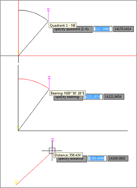
This command prompts you for a start point, followed by prompts to input the Quadrant, Bearing, and Distance values. You can enter values on the command line for each input, or you can graphically choose inputs by picking them on screen. The glyphs at each stage of input guide you in any graphical selections. After creating one line, you can continue drawing lines by bearing, or you can switch to any other method by clicking one of the other Line By commands on the Draw panel (see Figure 1-18).
Figure 1-18: The tooltips for a quadrant (top), a bearing (middle), and a distance (bottom)
Create Line By Azimuth Command
The Create Line By Azimuth command prompts you for a start point, followed by a north azimuth, and then a distance (Figure 1-19).
Figure 1-19: The tooltip for the Create Line by Azimuth command

Create Line By Angle Command
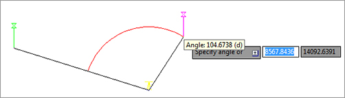
The Create Line By Angle command prompts you for a turned angle and then a distance (Figure 1-20). This command is useful when you’re creating linework from angles right (in lieu of angles left) and distances recorded in a traditional handwritten field book (required by law in many states).
Figure 1-20: The tooltip for the Create Line By Angle command
Create Line By Deflection Command
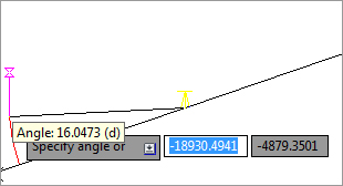
By definition, a deflection angle is the angle turned from the extension of a line from the backsight extending through an instrument. Although this isn’t the most frequently used surveying tool in this day of data collectors and GPSs, on some occasions you may need to create this type of line. When you use the Create Line By Deflection command, the command line and tooltips prompt you for a deflection angle followed by a distance (Figure 1-21). In some cases, deflection angles are recorded in the field in lieu of right angles.
Figure 1-21: The tooltips for the Create Line By Deflection command
Create Line By Station/Offset Command
To use the Create Line By Station/Offset command, you must have a Civil 3D Alignment object in your drawing. The line created from this command allows you to start and/or end a line on the basis of a station and offset from an alignment.
You’re prompted to choose the alignment and then input a station and offset value. The line begins at the station and offset value. On the basis of the tooltips, you might expect the line to be drawn from the alignment station at offset zero and out to the alignment station at the input offset. This isn’t the case.
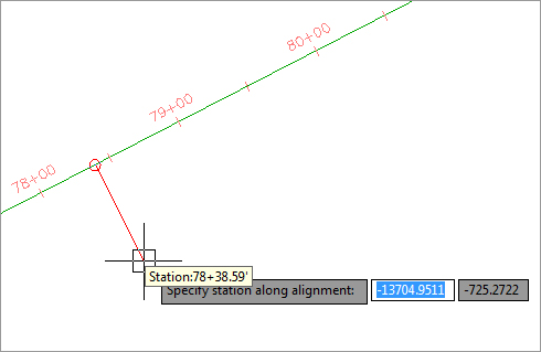
When prompted for the station, you’re given a tooltip that tracks your position along the alignment, as shown in Figure 1-22. You can graphically choose a station location by picking in the drawing (including using your osnaps to assist you in locking down the station of a specific feature). Alternatively, you can enter a station value on the command line.
Figure 1-22: The Create Line By Station/Offset command provides a tooltip for you to track stationing along the alignment.
Once you’ve selected the station, you’re given a tooltip that is locked on that particular station and tracks your offset from the alignment (see Figure 1-23). You can graphically choose an offset by picking in the drawing, or you can type an offset value on the command line.
Figure 1-23: The Create Line By Station/Offset command provides a tooltip that helps you track the offset from the alignment.

Create Line By Side Shot Command
The Create Line By Side Shot command lets you occupy one point, designate a backsight, and draw a line that has endpoints relative to that point. The occupied point represents the setup of your surveying station, whereas the second point represents your surveying backsight. This tool may be most useful when you’re creating stakeout information or re-creating data from field notes. If you know where your crew set up and you have their side-shot angle measurements but you don’t have electronic information to download, this tool can help. To specify locations relative to your occupied point, you can specify the angle, bearing, deflection, or azimuth on the command line or pick locations in your drawing. In some cases, it is more appropriate to supply a survey crew with handwritten notes regarding backsights, foresights, angles right, and distances rather than upload the same information to a data collector.
While the command is active, you can toggle between angle, bearing, deflection, and azimuth by following the command-line prompts.
When you’re using the Create Line By Side Shot command, you’re given a setup glyph at your occupied point, a backsight glyph, and a tooltip to track the angle, bearing, deflection, or azimuth of the side shot (see Figure 1-24). You can toggle between these options by following the command-line prompts.
Figure 1-24: The tooltip for the Create Line By Side Shot command tracks the angle, bearing, deflection, or azimuth of the side shot.

Create Line Extension Command
The Create Line Extension command is similar to the AutoCAD Lengthen command. This command allows you to add length to a line or specify a desired total length of the line.
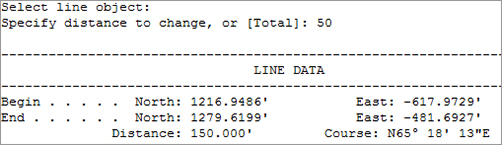
You are first prompted to choose a line. The command line then displays the prompt Specify distance to change, or [Total]. The distance you specify is added to the existing length of the line. The command draws the line appropriately and provides a short summary report on that line. The summary report in Figure 1-25 indicates that the beginning line length was 100″ and that an additional distance of 50″ was specified with the Line Extension command. It is important to note that in some cases, it may be more desirable to create a line by a turned angle or deflection of 180 degrees so as not to disturb linework originally created from existing legally recorded documents.
Figure 1-25: The Create Line Extension command provides a summary of the changes to the line.
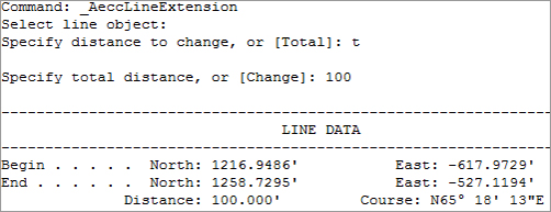
If instead you specify a total distance on the command line, the length of the line is changed to the distance you specify. The summary report shown in Figure 1-26 indicates that the beginning of the line was the same as in Figure 1-26 but with a total length of only 100″.
Figure 1-26: The summary report on a line where the command specified a total distance
Create Line From End Of Object Command
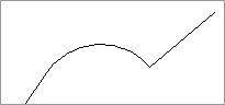
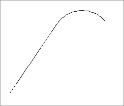
The Create Line From End Of Object command lets you draw a line tangent to the end of a line or arc of your choosing. Most commonly, you’ll use this tool when re-creating deeds or other survey work where you have to specify a line that continues a tangent from an arc (see Figure 1-27).
Figure 1-27: The Create Line From End Of Object command lets you add a tangent line to the end of an arc.
Create Line Tangent From Point Command
The Create Line Tangent from Point command is similar to the Create Line From End Of Object command, but Create Line Tangent From Point allows you to choose a point of tangency that isn’t the endpoint of the line or arc (see Figure 1-28).
Figure 1-28: The Create Line Tangent From Point command can place a line tangent at the midpoint of an arc (or line).

Create Line Perpendicular From Point Command
Using the Create Line Perpendicular From Point command, you can specify that you’d like a line drawn perpendicular to any point of your choosing. In the example shown in Figure 1-29, a line is drawn perpendicular to the endpoint of the arc. This command can be useful when the distance from a known monument perpendicular to a legally platted line must be labeled in a drawing.
Figure 1-29: A perpendicular line is drawn from the endpoint of an arc, using the Create Line Perpendicular From Point command.