
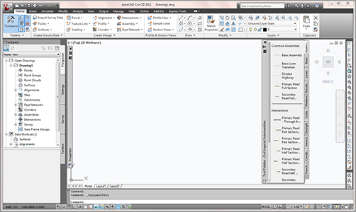
If you have used Civil 3D 2010 or 2011, the interface for Civil 3D 2012 is basically the same. If you are coming into Civil 3D 2012 from an earlier release, then this part of the chapter is for you. The context-sensitive Ribbon is one of the biggest differences you will encounter. The tools within Civil 3D can now be accessed via the Ribbon. Toolspace and the general look and feel of the Civil 3D interface make this release easy to use. Figure 1-1 shows the Civil 3D palette sets along with the AutoCAD tool palettes and context-sensitive Ribbon displayed in a typical environment.
Figure 1-1: Civil 3D in a typical environment. Toolspace is docked on the left, and tool palettes float over the drawing window. The Ribbon is at the top of the workspace.
Toolspace
Toolspace is one of the unique Civil 3D palette sets. Toolspace can have as many as four tabs to manage user data. These tabs are as follows:
- Prospector
- Settings
- Survey
- Toolbox
Using a Microsoft Windows Explorer–like interface within each, these tabs drive a large portion of the user control and data management of Civil 3D.
Prospector
Prospector is the main window into the Civil 3D object model. This palette, or tab, is where you go seeking data; it also shows points, alignments, parcels, corridors, and other objects as one concise, expandable list. In addition, in a project environment this window is where you control access to your project data, create references to shared project data, and observe the check-in and check-out status of a drawing. Finally, you can also use Prospector to create a new drawing from the templates defined in the Drawing Template File Location branch in your AutoCAD Options dialog. Prospector has the following branches:
- Open Drawings
- Projects (only if the Vault client is installed)
- Data Shortcuts
- Drawing Templates
Master and Active Drawing Views
If you can’t see the Projects or Drawing Templates branch in Figure 1-1, look at the top of the Prospector pane. There is a drop-down menu for operating in Active Drawing View or Master View mode. Selecting Active Drawing View displays only the active drawing and data shortcuts. Master View mode, however, displays the Projects, the Drawing Templates, and the Data Shortcuts branches, as well as the branches of all drawings that are currently open.
In addition to the branches, Prospector has a series of icons across the top that toggle various settings on and off. Some of the Civil 3D icons from previous versions have been removed, and their functionality has been universally enabled for Civil 3D 2012. Let’s take a closer look at those icons:
Item Preview Toggle Turns on and off the display of the Toolspace item preview within Prospector. These previews can be helpful when you’re navigating drawings in projects (you can select one to check out) or when you’re attempting to locate a parcel on the basis of its visual shape. In general, however, you can turn off this toggle—it’s purely a user preference.
Preview Area Display Toggle When Toolspace is undocked, this button moves the preview area from the right of the tree view to beneath the tree view area.
Panorama Display Toggle Turns on and off the display of the Panorama window (which we’ll discuss in a bit). To be honest, there doesn’t seem to be a point to this button, but it’s here nonetheless.
Help This should be obvious, but it’s amazing how many people overlook this icon.
Have You Looked in the Help File Lately?
The AutoCAD Civil 3D development team in Manchester, New Hampshire, has worked hard to make the Help files in Civil 3D top-notch and user friendly. The help files should be your first line of support!
Open Drawings
This branch of Prospector contains the drawings currently open in Civil 3D. Each drawing is subdivided into groups by major object type, such as points, point groups, surfaces, and so forth. These object groups then allow you to view all the objects in the collection. Some of these groups are empty until objects are created. You can learn details about an individual object by expanding the tree and selecting an object.
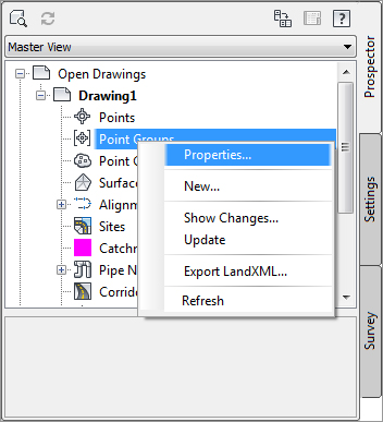
Within each drawing, the breakdown is similar. If a collection isn’t empty, a plus sign appears next to it, as in a typical Windows Explorer interface. Selecting any of these top-level collection names displays a list of members in the preview area. Right-clicking the collection name allows you to select various commands that apply to all the members of that collection. For example, right-clicking the Point Groups collection brings up the menu shown in Figure 1-2.
Figure 1-2: Context-sensitive menus in Prospector
In addition, right-clicking the individual object in the list view offers many commands unique to Civil 3D: Zoom To Object and Pan To Object are typically included. By using these commands, you can find any parcel, point, cross section, or other Civil 3D object in your drawing almost instantly.
Many longtime users of AutoCAD have resisted right-clicking menus for their daily tasks since AutoCAD 14. In other AutoCAD products this may be possible, but in Civil 3D you’ll miss half the commands! This book focuses on the specific options and commands for each object type during discussions of the particular objects.
Projects
The Projects branch of Prospector will only be visible if you are using Vault. This branch allows you to sign in and out of Vault, review what projects are available, manage the projects you sort through for information, check out drawings for editing, and review the status of drawings as well as that of individual project–based objects.
Data Shortcuts
A data shortcut identifies the path to a specific object, in a specific drawing. Many users have found data shortcuts to be ideal in terms of project collaboration for two reasons: flexibility and simplicity.
Drawing Templates
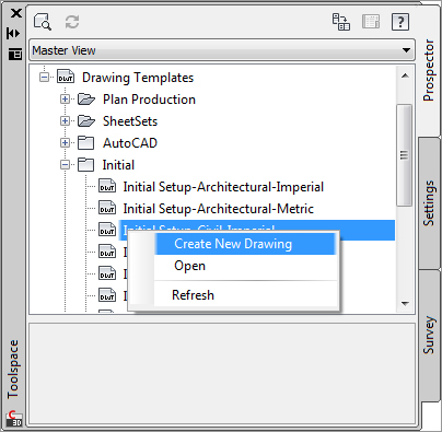
The Drawing Templates branch is added more as a convenience than anything else. You can still create new drawings via the standard File New option, but by using the Drawing Templates branch, you can do the same thing without leaving Prospector. The Drawing Templates branch searches the file path specified in your AutoCAD Options dialog and displays a list of all the DWT files it finds. You can customize this path to point to a server or other folder, but by default it’s a local user-settings path. Right-clicking the name of a template presents you with the options shown in Figure 1-3.
Figure 1-3: Creating a new drawing from within the Drawing Templates branch of Prospector. The templates shown here are located in the folder set in your AutoCAD Options dialog.
Civil 3D is built on both AutoCAD and AutoCAD Map, so Civil 3D 2012 comes with a variety of templates. However, most users will want to select one of the top few templates, which start with _Autodesk Civil 3D and then have some descriptive text. These templates have been built on the basis of customer feedback to provide Civil 3D with a varying collection of object styles. These templates give you a good starting point for creating a template that meets your needs or the needs of your firm.
Settings
The Settings tab of Toolspace is where you can adjust how Civil 3D objects look and how the Civil 3D commands work. You use this tab to control styles, labels, and command settings for each component of Civil 3D. This book starts by looking at the top level of drawing settings and a few command settings to get you familiar, and then covers the specifics for each object’s styles and settings in their respective chapters.
Drawing Settings
Starting at the drawing level, Civil 3D has a number of settings that you must understand before you can use the program efficiently. Civil 3D understands that the end goal of most users is to prepare construction documents on paper. To that end, most labeling and display settings are displayed in inches for imperial users and millimeters for metric users instead of nominal units like many other AutoCAD objects. Because much of this is based on an assumed working scale, let’s look at how to change that setting, along with some other drawing options:
1. Open the file Basic Site.dwg from this book’s companion web page, www.sybex.com/go/masteringcivil3d2012.
2. Switch to the Settings tab.
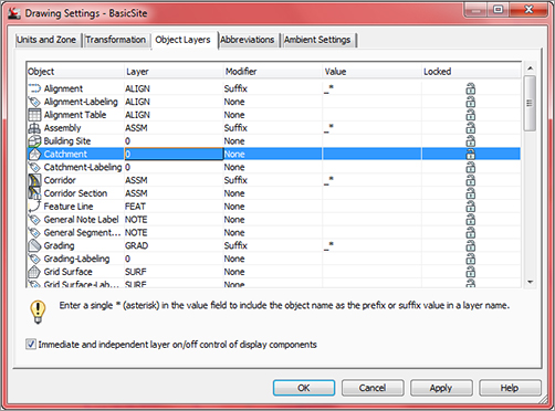
3. Right-click the filename, and select Edit Drawing Settings to display the dialog shown in Figure 1-4.
Figure 1-4: The Drawing Settings dialog

Each tab in this dialog controls a different aspect of the drawing. Most of the time, you’ll pick up the object layers, abbreviations, and ambient settings from a companywide template. However, the drawing scale and coordinate information change for every job, so you’ll visit the Units And Zone and the Transformation tabs frequently.
Units And Zone Tab
The Units And Zone tab lets you specify metric or imperial units for your drawing. You can also specify the conversion factor between systems. In addition, you can control the assumed plotting scale of the drawing. The drawing units typically come from a template, but the options for scaling blocks and setting AutoCAD variables depend on your working environment. Many engineers continue to work in an arbitrary coordinate system using the settings as shown earlier, but using a real coordinate system is easy! For example, setting up a drawing for the Harrisburg, Pennsylvania area, you’d follow this procedure:
1. Select USA, Pennsylvania from the Categories drop-down menu on the Units And Zone tab.
2. Select NAD83 Pennsylvania State Planes, South Zone, US Foot from the Available Coordinate Systems drop-down menu. You could have also typed PA83-SF in the Coordinate System Code box.
There are literally hundreds, if not thousands, of available coordinate systems. These are established by international agreement; because Civil 3D is a worldwide product, almost any recognized surveying coordinate system can be found in the options. Once your coordinate system has been established, you can change it on the Transformation tab if desired.
This tab also includes the options Scale Objects Inserted From Other Drawings and Set AutoCAD Variables To Match. In Figure 1-4, both are unchecked to move forward.
The Scaling option has been problematic in the past because many firms work with drawings that have no units assigned and therefore scale incorrectly. But you can experiment with this setting as you’d like. The Set AutoCAD Variables To Match option attempts to set the AutoCAD variables AUNITS, DIMUNITS, INSUNITS, and MEASUREMENT to the values placed in this dialog. You can learn about the nature of these variables via the help files. Because of some inconsistencies between coordinate-based systems and the AutoCAD engine, sometimes these variables must be approximated. Again, you won’t typically set this flag to True; you should experiment in your own office to see if it can help you.
Transformation Tab
With a base coordinate system selected, you can now do any further refinement you’d like using the Transformation tab (Figure 1-5). The coordinate systems on the Units And Zone tab can be refined to meet local ordinances, tie in with historical data, complete a grid to ground transformation, or account for minor changes in coordinate system methodology. These changes can include the following:
Figure 1-5: The Transformation tab

Apply Sea Level Scale Factor Takes into account the mean elevation of the site and the spheroid radius that is currently being applied as a function of the selected zone ellipsoid.
Grid Scale Factor Based on a 1:1 value, a user-defined uniform scale factor, a reference point scaling, or a prismoidal transformation in which every point in the grid is adjusted by a unique amount.
Reference Point Can be used to set a singular point in the drawing field via pick or via point number, local northing and easting, or grid northing and easting values.
Rotation Point Can be used to set the reference point for rotation via the same methods as the reference point.
Specify Grid Rotation Angle Enter an amount or set a line to North by picking an angle or deflection in the drawing. You can use this same method to set the azimuth if desired.
Most engineering firms work on either a defined coordinate system or an arbitrary system, so none of these changes are necessary. Given that, this tab will be your only method of achieving the necessary transformation for certain surveying and geographic information system (GIS)–based and land surveying–based tasks.
Object Layers Tab
Setting object layers to your company standard is a major part of creating the feel you’re after when using Civil 3D in your office. The nearly 50 objects described here make up the entirety of the Civil 3D modeling components and the objects you and other users will deal with daily.
Let’s see how to change a parameter in the Object Layers tab. First, click the Layer column in the Catchment row, as shown in Figure 1-6. Then in the Layer Selection dialog, select _CATCHMENT and click OK.
Figure 1-6: Changing the Layer setting for the Catchment object
One Object at a Time
Note that this procedure only changes the Catchment object. If you want to change the standard of all the objects, you need to adjust the Catchment Labeling, Catchment Table, Profile, Profile View, Profile View Labeling, and so on. To do this, it’s a good idea to right-click in the grid view and select Copy All. You can then paste the contents of this matrix into Microsoft Excel for easy formatting and reviewing.
One common question that surrounds the Object Layers tab is the check box at the lower left: Immediate And Independent Layer On/Off Control Of Display Components. What the heck does that mean? Relax—it’s not as complicated as it sounds.
Many objects in Civil 3D are built from underlying components. Take an alignment, for example. It’s built from tangents, curves, spirals, extension lines, and so on. Each of these components can be assigned its own layer—in other words, the lines could be assigned to the LINES layer, curves to the CURVES layer, and so on. When this check box is selected, the component’s layer exerts some control. In the example given, if the alignment is assigned to the ALIGN layer and the box is selected, turning off (not freezing) the LINES layer will make the line components of that alignment disappear. Deselect this control, and the LINES layer’s status won’t have any effect on the visibility of the alignment line components.
Finally, it’s important to note that this layer control determines the object’s parent layer at creation. Civil 3D objects can be moved to other layers at any time. Changing this setting doesn’t change any objects already in place in the drawing.
Abbreviations Tab
You could work for years without noticing the Abbreviations tab. The options on this tab allow you to set the abbreviations Civil 3D uses when labeling items as part of its automated routines. The prebuilt settings are based on user feedback, and many of them are the same as the settings from Land Desktop, the last-generation civil engineering product from Autodesk.
Changing an abbreviation is as simple as clicking in the Value field and typing a new one. Notice that the Alignment Geometry Point Entity Data section has a larger set of values and some formulas attached. They are more representative of other label styles, and we’ll visit the label editor in Chapter 19, Styles.
Ambient Settings Tab
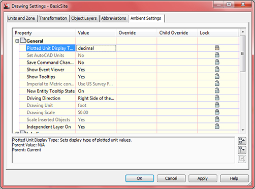
The Ambient Settings tab can be daunting at first. The term ambient means “surround” or “surrounding,” and these settings control many of the math, labeling, and display features, as well as the user interaction surrounding the use of Civil 3D. Being familiar with the way this tab works will help you further down the line, because almost every other setting dialog in the program works like the one shown in Figure 1-7.
Figure 1-7: The Ambient Settings tab with the General branch expanded
You can approach this tab in the following ways:
Top to Bottom Expand one branch, handle the settings in that branch, and then close it and move to the next.
Print and Conquer Expand all the branches using the Expand All Categories button found at the lower right.
Drawing Precision vs. Label Precision
You can create label styles (discussed in Chapter 19, “Styles”) to annotate objects using precision, units, or specifications other than those set in the Ambient or Command Settings dialog. Establish settings to reflect how you’d like to input and track your data, not necessarily how you’d like to label your data.
The Ambient Settings for Direction offer the following choices:
- Unit: Degree, Radian, and Grad
- Precision: 0 through 8 decimal places
- Rounding: Round Normal, Round Up, and Truncate
- Format: Decimal, two types of DDMMSS, and Decimal DMS
- Direction: Short Name (spaced or unspaced) and Long Name (spaced or unspaced)
- Capitalization
- Sign
- Measurement Type: Bearings, North Azimuth, and South Azimuth
- Bearing Quadrant
From this list, it becomes clear where these settings apply to the tools discussed in this chapter. When you’re using the Bearing Distance transparent command, for example, these settings control how you input your quadrant, your bearing, and the number of decimal places in your distance.
Explore the other categories, such as Angle, Lat Long, and Coordinate, and customize the settings to fit how you work.
At the bottom of the Ambient Settings tab is a Transparent Commands category. These settings control how (or if) you’re prompted for the following information:
Prompt For 3D Points Controls whether you’re asked to provide a z elevation after x and y have been located.
Prompt For Y Before X For transparent commands that require x and y values, this setting controls whether you’re prompted for the y-coordinate before the x-coordinate. Most users prefer this value set to False so they’re prompted for an x-coordinate and then a y-coordinate.
Prompt For Easting Then Northing For transparent commands that require Northing and Easting values, this setting controls whether you’re prompted for the Easting first and the Northing second. Most users prefer this value set to False, so they’re prompted for Northing first and then Easting.
Prompt For Longitude Then Latitude For transparent commands that require longitude and latitude values, this setting controls whether you’re prompted for Longitude first and Latitude second. Most users prefer this set to False, so they’re prompted for Latitude and then Longitude.
After you have expanded the branches, right-click in the middle of the displayed options and select Copy To Clipboard. Then paste the settings to Excel for review, as you did with the Object Layers tab.
Sharing the Workload
The print and conquer approach makes it easy to distribute multiple copies to surveyors, land planners, engineers, and so on and let them fill in the changes. Then, creating a template for each group is a matter of making their changes. If you’re asking end users who aren’t familiar with the product to make these changes, it’s easy to miss one. Working line by line is fairly foolproof.
After you decide how to approach these settings, get to work. The settings are either drop-down menus or text boxes (in the case of numeric entries). Many of them are self-explanatory and common to land-development design. Let’s look at these settings in more detail (see Figure 1-7).
Plotted Unit Display Type Remember, Civil 3D knows you want to plot at the end of the day. In this case, it’s asking you how you would like your plotted units measured. For example, would you like that bit of text to be 0.25″ tall or ¼″ high? Most engineers are comfortable with the Leroy method of text heights (L80, L100, L140, and so on), so the decimal option is the default.
Set AutoCAD Units This displays whether or not Civil 3D should attempt to match AutoCAD drawing units, as specified on the Units And Zone tab.
Save Command Changes To Settings This setting is incredibly powerful but a secret to almost everyone. By setting it to Yes, your changes to commands will be remembered from use to use. This means if you make changes to a command during use, the next time you call that Civil 3D command, you won’t have to make the same changes. It’s frustrating to do work over because you forgot to change one out of the five things that needed changing, so this setting is invaluable.
Show Event Viewer Event Viewer is Civil 3D’s main feedback mechanism, especially when things go wrong. It can get annoying, however, and it takes up valuable screen real estate (especially if you’re stuck with one monitor!), so many people turn Show Event Viewer off. We recommend leaving it on and pushing it to the side if needed.
Show Tooltips One of the cool features that people remark on when they first use Civil 3D is the small pop-up that displays relevant design information when the cursor is paused on the screen. This includes things such as Station-Offset information, Surface Elevation, Section information, and so on. Once a drawing contains numerous bits of information, this display can be overwhelming; therefore, Civil 3D offers the option to turn off these tooltips universally with this setting. A better approach is to control the tooltips at the object type by editing the individual feature settings. You can also control the tooltips by pulling up the properties for any individual object and looking at the Information tab.
Imperial To Metric Conversion This displays the conversion method specified on the Units And Zone tab. The two options currently available are US Survey Foot and International Foot.
New Entity Tooltip State You can also control tooltips on an individual object level. For instance, you might want tooltip feedback on your proposed surface but not on the existing surface. This setting controls whether the tooltip is turned on at the object level for new Civil 3D objects.
Driving Direction This specifies the side of the road that forward-moving vehicles use for travel. This setting is important in terms of curb returns and intersection design.
Drawing Unit, Drawing Scale, and Scale Inserted Objects These settings were specified on the Units And Zone tab but are displayed here for reference and so that you can lock them if desired.
Independent Layer On This is the same control that was set on the Object Layers tab.
The settings that are applied here can also be applied at the object levels. For example, you may typically want elevation to be shown to two decimal places, but when looking at surface elevations, you might want just one. The Override and Child Override columns give you feedback about these types of changes. See Figure 1-8.
Figure 1-8: The Child Override indicator in the Elevation values

The Override column shows whether the current setting is overriding something higher up. Because you’re at the Drawing Settings level, these are clear. However, the Child Override column displays a down arrow, indicating that one of the objects in the drawing has overridden this setting. After a little investigation through the objects, you’ll find the override is in the Edit Feature Settings of the Profile view, as shown in Figure 1-9.
Figure 1-9: The Profile Elevation Settings and the Override indicator

Notice that in this dialog, the box is checked in the Override column. This indicates that you’re overriding the settings mentioned earlier, and it’s a good alert that things have changed from the general Drawing Settings to this Object Level setting.
But what if you don’t want to allow those changes? Each Settings dialog includes one more column: Lock. At any level, you can lock a setting, graying it out for lower levels. This can be handy for keeping users from changing settings at the lower level that perhaps should be changed at a drawing level, such as sign or rounding methods.
Object Settings
If you click the Expand button next to the drawing name, you see the full array of objects that Civil 3D uses to build its design model. Each of these has special features unique to the object being described, but there are some common features as well. Additionally, the General collection contains settings and styles that are applied to various objects across the entire product.
The General collection serves as the catchall for styles that apply to multiple objects and for settings that apply to no objects. For instance, the Civil 3D General Note object doesn’t really belong with the Surface or Pipe collection. It can be used to relate information about those objects, but because it can also relate to something like “Don’t Dig Here!” it falls into the General category. The General collection has three components (or branches):
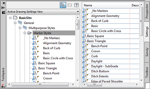
Multipurpose Styles These styles are used in many objects to control the display of component objects. The Marker Styles and Link Styles collections are typically used in cross-sectional views, whereas the Feature Line Styles collection is used in grading and other commands. Figure 1-10 shows the collection of multipurpose styles and some of the marker styles that ship with the product.
Figure 1-10: General multipurpose styles and some marker styles
Label Styles The Label Styles collection allows Civil 3D users to place general text notes or label single entities outside the parcel network while still taking advantage of Civil 3D’s flexibility and scaling properties. With the various label styles shown in Figure 1-11, you can get some idea of their usage.
Figure 1-11: Line label styles
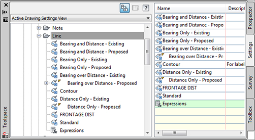
Because building label styles is a critical part of producing plans with Civil 3D, Chapter 19, “Styles,” looks at how to build a new basic label and some of the common components that appear in every label style throughout the product.
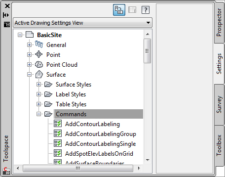
Commands Almost every branch in the Settings tree contains a Commands folder. Expanding this folder, as shown in Figure 1-12, shows you the typical long, unspaced command names that refer to the parent object.
Figure 1-12: Surface command settings in Toolspace
Survey
The Survey palette is displayed optionally and controls the use of the survey, equipment, and figure prefix databases. Survey is an essential part of land-development projects. Because of the complex nature of this tab, all of Chapter 2, “Survey,” is devoted to it.
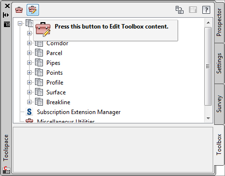
Toolbox
The Toolbox is a launching point for add-ons and reporting functions. To access the Toolbox, from the Home tab in the Ribbon, select Toolspace Palettes Toolbox. Out of the box, the Toolbox contains reports created by Autodesk, but you can expand its functionality to include your own macros or reports. The buttons on the top of the Toolbox, shown in Figure 1-13, allow you to customize the report settings and add new content.
Figure 1-13: The Toolbox palette with the Edit Toolbox Content button
A Toolbox Built Just for You
You can edit the Toolbox content and the Report Settings by selecting the desired tool, right-clicking, and then executing. Don’t limit yourself to the default reports that ship in the Toolbox, though. Many firms find that adding in-house customizations to the Toolbox gives them better results and is more easily managed at a central level than by customizing via the AutoCAD custom user interface (CUI) and workspace functionality.
Let’s add one of the sample Civil 3D Visual Basic Application (VBA) macros to a new Toolbox:
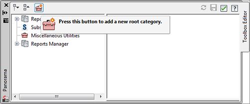
1. Click the Edit Toolbox Content button (shown in Figure 1-13) to open the Toolbox Editor in Panorama.
2. Click the button shown here to add a new root category.
3. Click the Root Category1 toolbox that appears. The name will appear in the preview area, where you can edit it. Change the name to Sample Files, and press ↵.
4. Right-click the Sample Files toolbox, and select New Category as shown here.

5. Expand the Sample Files toolbox to view the new category, and then click the name to edit it in the preview area. Change the name to VBA, and press ↵.
6. Right-click the VBA category, and select New Tool.
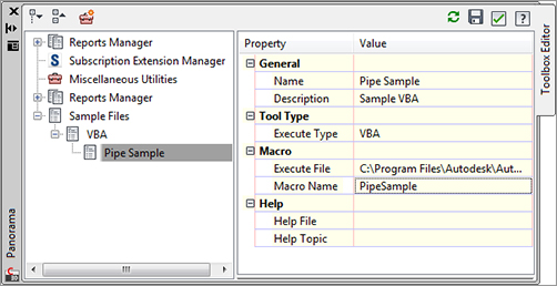
7. Expand the VBA category to view the new tool, and then click the name to edit it in the preview area. Change its name to Pipe Sample.
8. Change the description to Sample VBA.
9. Working down through the properties in the preview area, select VBA in the drop-down menu in the Execute Type field.
10. Click in the Execute File field, and then click the More button.
11. Browse to C:Program FilesAutocad Civil 3D 2012SampleCivil 3D APICOMVbaPipe, and select the file PipeSample.dvb.
12. Click Open.
13. Click in the Macro Name text field, and type PipeSample as shown here.
14. Click the green check box at the upper right to dismiss the editor.
15. You will be asked, “Would you like to apply those changes now?” Select Yes.
You’ve now added that sample VBA macro to your Toolbox. By adding commonly used macros and custom reports to your Toolbox, you can keep them handy without modifying the rest of your Civil 3D interface or programming buttons. It’s just one more way to create an interface and toolset for the way you work.
Panorama
The Panorama window is Civil 3D’s feedback and tabular editing mechanism. It’s designed to be a common interface for a number of different Civil 3D–related tasks, and you can use it to provide information about the creation of profile views, to edit pipe or structure information, or to run basic volume analysis between two surfaces. For an example of Panorama in action, change to the View tab, and then select Palettes Event Viewer. You’ll explore and use Panorama more during this book’s discussion of specific objects and tasks.
Running Out of Screen Real Estate?
It’s a good idea to turn on Panorama using this technique and then drag it to the side so you always see any new information. Although it’s possible to turn it off, doing so isn’t recommended—you won’t know when Civil 3D is trying to tell you something! Place Panorama on your second monitor (now you see why you need to have a second monitor, don’t you?), and you’ll always be up-to-date with your Civil 3D model.
And in case you missed it, you were using Panorama when you added the sample VBA macro in the previous exercise.
Ribbon
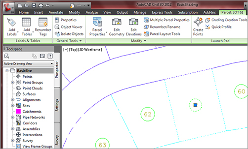
As with AutoCAD, the Ribbon is the primary interface for accessing Civil 3D commands and features. When you select an AutoCAD Civil 3D object, the Ribbon displays commands and features related to that object. If several object types are selected, the Multiple contextual tab is displayed. Use the following procedure to familiarize yourself with the Ribbon:
1. Open the BasicSite.dwg, which you will find at www.sybex.com/go/masteringcivil3d2012.
2. Select one of the parcel labels (the labels in the middle of the lot areas).
3. Notice that the Labels & Tables, General Tools, Modify, and Launch Pad tabs are displayed, as shown in Figure 1-14.
Figure 1-14: The context-sensitive Ribbon
4. Select a parcel line and notice the display of the Multiple contextual tab.
5. Use the Esc key to cancel all selections.
6. Reselect a parcel line. Select the down arrow next to the Modify panel. Using the pin at the bottom-left corner of the panel, pin the panel open.
7. Select the Properties command in the General Tools panel to open the AutoCAD Properties palette. Notice that the Modify panel remains opened and pinned.
Styles and More Styles
Civil 3D uses styles to change the look and feel of objects and labels. Throughout this book, you will see many styles. For a better look at styles, refer to Chapter 19.