
Working with Grading Feature Lines
There are two types of feature lines: corridor feature lines and grading feature lines. Corridor feature lines are discussed in Chapter 9, “Basic Corridors,” and grading feature lines are the focus of this chapter. It’s important to note that grading feature lines can be extracted from corridor feature lines, and you can choose whether or not to dynamically link them to the host object.
As discussed in Chapter 4, “Surfaces,” terrain modeling can be defined as the manipulation of triangles created by connecting points and vertices to achieve Delaunay triangulation. In Land Desktop (LDT) and other software, this is often done with the use of native 3D polylines. In Civil 3D, the creation of the feature line object adds a level of control and complexity not available to 3D polylines. In this section, you look at the feature line, various methods of creating feature lines, some simple elevation edits, planar editing functionality, and labeling of the newly created feature lines.
Accessing Grading Feature Line Tools
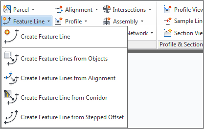
The Feature Line creation tools can be accessed from the Home tab’s Create Design panel, as shown in Figure 15-1.
Figure 15-1: The Feature Line drop-down menu on the Create Design panel
The Feature Line editing tools can be accessed via the Design panel on the Modify tab, or via the Feature Line context tab that’s available after you select an existing feature line (see Figure 15-2).
Figure 15-2: The Feature Line context tab accessed by selecting an existing feature line

One thing to remember when working with feature lines is that they do belong in a site. Feature lines within the same site snap to each other in the vertical direction and can cause some confusion when you’re trying to build surfaces. If you’re experiencing some weird elevation data along your feature line, be sure to check out the parent site. If the concept of a parent site or sites in general doesn’t make much sense to you, be sure and look at Chapter 5, “Parcels,” before going too much further. Sites are a major part of the way feature lines interact with each other, and many users who have problems with grading completely ignore sites as part of the equation.
The next few sections break down the various tools in detail. You’ll use almost all of them in this chapter, so in each section you’ll spend some time getting familiar with the available tools and the basic concepts behind them.
Creating Grading Feature Lines
There are five primary methods for creating feature lines, as shown in Figure 15-1. They generate similar results but have some key differences:
- The Create Feature Line tool allows you to create a feature line from scratch, assigning elevations as you go. These elevations can be based on direct data input at the command line, slope information, or surface elevations.
- The Create Feature Lines From Objects tool converts lines, arcs, polylines, and 3D polylines into feature lines. This process also allows elevations to be assigned from a surface or grading group.
- The Create Feature Lines From Alignment tool allows you to build a new feature line from an alignment, using a profile to assign elevations. This feature line can be dynamically tied to the alignment and the profile, making it easy to generate 3D design features based on horizontal and vertical controls.
- The Create Feature Line From Corridor command is used to export a grading feature line from a corridor feature line.
- The Create Feature Line From Stepped Offset tool is used to create a feature line from an offset and the difference in elevation from a feature line, survey figure, polyline, or 3D polyline.
You explore each of these methods in the next few exercises. In this exercise, you will be creating a swale from feature lines.
1. Open the CreatingFeatureLines.dwg file. (Remember, all data can be downloaded from www.sybex.com/go/masteringcivil3d2012.) This drawing has the outer base line of the subdivision drawn and an overland swale.
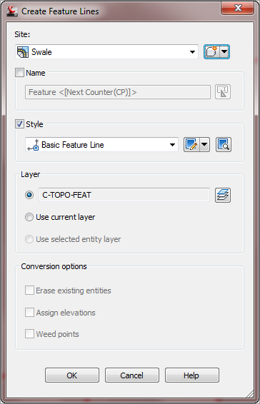
2. Change to the Home tab and select Feature Line Create Feature Line from the Create Design panel to display the Create Feature Lines dialog. We need to create a new site in which to put the swale. Just like parcels, grading objects will react with like objects in a site. So by isolating this swale, we can ensure that everything will be drawn properly before committing it to a site. Or you can always leave it on the created site and then create composite surfaces (see Chapter 4 for more information on composite surfaces).
3. Click the Create New button to the right of the site name. The Site Properties dialog opens. Enter Swale for the name of this site and click OK. The Create Feature Lines dialog should now look like Figure 15-3.
Figure 15-3: The Create Feature Lines dialog
4. Click OK. The command prompt now reads Specify start point:.
5. Use an Endpoint osnap to pick the line on the right (closest to the red line).
6. Enter S↵ at the command line to use a surface to set elevation information. In the Select Surface dialog, use the drop-down to choose EG and click OK.
7. Press ↵ to accept the elevation offered.
8. Use an Endpoint osnap to pick the end of the left side of the line.
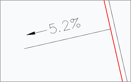
9. Enter -5.2↵ to set the grade between points.
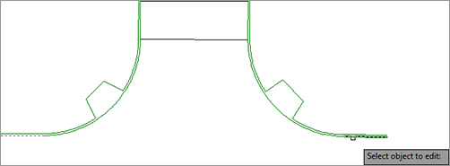
10. Press ↵ to exit the command. Your screen should look like Figure 15-4.
Figure 15-4: Setting the grade between points
Looking back at Figure 15-3, note that there is an unused option for assigning a Name value to each feature line. Using names does make it easier to pick feature line objects if you decide to use them for building a corridor object. The Name option is available for each method of creating feature line objects, but will generally be ignored for this chapter except for one exercise covering the renaming tools available.
This method of creating a feature line connecting a few points seems pretty tedious to most users. In the next exercise, you convert an existing polyline to a feature line and set its elevations on the fly:
1. Open the CreatingFeatureLines.dwg file if it isn’t open already.
2. Change to the Home tab and choose Feature Line Create Feature Lines From Objects from the Create Design panel.
3. Pick the red closed polyline representing the limits of grading.
4. Right-click and select Enter, or press ↵. The Create Feature Lines dialog will appear. Put the polyline on a site called Rough Grading. This will be the beginning of our overall grading plan.
There are some differences in the Create Feature Lines dialog from that shown on Figure 15-3. Notably, the Conversion Options near the bottom of the dialog are now active, so take a look at the options presented:
- Erase Existing Entities removes the object onscreen and replaces it with a feature line object. This avoids the creation of duplicate linework, but could be harmful if you wanted your linework for planimetric purposes.
- Assign Elevations lets you set the feature line point of intersection (PI) elevations from a surface or grading group, essentially draping the feature line on the selected object.
- Weed Points decreases the number of nodes along the object. This option is handy when you’re converting digitized information into feature lines.
5. Check the Assign Elevations box. The Erase Existing Entities option is on by default, and you will not select the Weed Points option.
6. Click OK to display the Assign Elevations dialog. Here you can select a surface to pull elevation data from, or assign a single elevation to, all PIs.
7. Make sure that the EG surface is selected. Check the Insert Intermediate Grade Break Points option. This inserts a PI at every point along the feature line where it crosses an underlying TIN line.
8. Click OK.
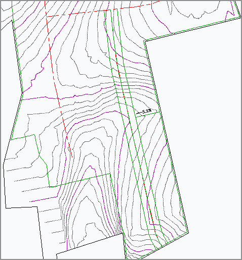
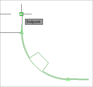
9. Pick the site outline (which is now the color green), and the grips will look like Figure 15-5.
Figure 15-5: Conversion to a feature line object

Note that in Figure 15-5 there are two types of grips: circular and square. Feature lines offer feedback via the grip shape. A square feature line grip indicates a full PI. This node can be moved in the x, y, and z directions, manipulating both the horizontal and vertical design. Circular grips are elevation points only. In this case, the elevation points are located at the intersection of the original polyline and the TIN lines existing in the underlying surface. Elevation points can only be slid along a given feature line segment, adjusting the vertical design, but cannot be moved in a horizontal plane. This combination of PIs and elevation points makes it easy to set up a long element with numerous changes in design grade that will maintain its linear design intent if the endpoints are moved.
Both of the methods used so far assume static elevation assignments for the feature line. They’re editable, but are not physically related to other objects in the drawing. This is generally acceptable, but sometimes it’s necessary to have a feature line that is dynamically related to an object. For grading purposes, it is often ideal to create a horizontal representation of a vertical profile along an alignment. Rather than build a corridor model as discussed in Chapters 9 and 10, a dynamic feature line can be extracted from a profile along an alignment, offset both horizontally and vertically, and used for grading. In the following example, a dynamic feature line is extracted from an alignment. Elevations for the vertices of the feature line are extracted from a profile, and finally, offset using the Create Feature Line From Stepped Offset tool to represent a swale.
1. Open the SteppedOffset.dwg file.
2. Change to the Home tab and select Feature Line Create Feature Lines From Alignment in the Create Design panel.
3. Select the Cabernet Court alignment at the lower portion of the site (the vertical alignment) to display the Create Feature Line From Alignment dialog. Make changes as shown in Figure 15-6. Note the Create Dynamic Link To The Alignment option near the bottom.
Figure 15-6: The Create Feature Line From Alignment dialog

4. Deselect the option to weed points, as shown in Figure 15-6. Click OK.
5. Change to the Home tab and select Feature Line Create Feature Line From Stepped Offset.
6. Enter 25 (7.62 m) at the command line and press ↵.
7. Select the dynamic feature line along the alignment.
8. Select a point to the right of the alignment when you see the prompt Specify side to offset or [Multiple]:.
9. The command prompt will offer you several choices for specifying elevations or grades to be used along the feature lines. If necessary, type the appropriate letters until the command prompt reads Specify elevation difference or [Grade/Slope/Elevation/Variable]:.
10. Enter 0 as the elevation difference at the command line and press ↵. This simply offsets the line from the road centerline to the right-of-way line. We will adjust this in a later exercise.
11. Repeat steps 8 through 10, but this time, pick a point to the left of the alignment. Your results should appear as shown in Figure 15-7. Leave this drawing open to use in the next exercise.
Figure 15-7: The completed alignment with offsets in place
If you click the alignment now, you will select the feature line, but you will not see any grips available. This is because the feature line is dynamically linked to the design profile along the alignment and can’t be modified. If either the alignment or the profile changes, the dynamic feature line will automatically update. Simply repeat the preceding procedure to create new offsets if needed. These three feature lines can be included in a new surface definition as breaklines, as discussed in Chapter 4.
Because dynamically linked feature line objects are slightly different, you’ll look at them in our next exercise before using the name and style buttons to update all the feature lines:
1. This exercise uses the dynamic feature line created in the previous exercise. Pan or zoom to view the feature line along the Cabernet Court alignment.
2. Select the feature line.
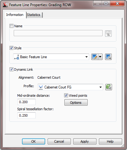
3. Choose Feature Line Properties from the Modify panel to open the Feature Line Properties dialog, as shown in Figure 15-8. The information displayed on the Information tab is unique to the dynamic feature line, and you still have some level of control over the linking options.
Figure 15-8: The Feature Line Properties dialog for an alignment-based feature line
4. Deselect the Dynamic Link option and click OK. Notice the grips appear. The dynamic relationship between the feature line and the alignment has been severed.
5. Select Feature Line Properties from the Modify panel and notice the Dynamic Link options have disappeared.
6. Select the two feature lines opposite the alignment.
7. Choose Apply Feature Line Styles from the Modify panel. The Apply Feature Line Style dialog will appear.
8. Select the Corridor Ditch style from the Style drop-down list and click OK to dismiss the dialog.
Many people don’t see much advantage in using styles with feature line objects, but there is one major benefit: linetypes. Zoom in on the feature lines on either side of the alignment and you’ll see the Grading Ditch style has a dashed linetype. 3D polylines do not display linetypes, but feature lines do. If you need to show the linetypes in your grading, feature line styles are your friend.
In the Feature Line context menu activated by selecting a feature line, several more commands can be found on the Modify panel, as shown in Figure 15-9, that are worth examining before we get into editing objects.
Figure 15-9: The Modify panel on the context Feature Line tab
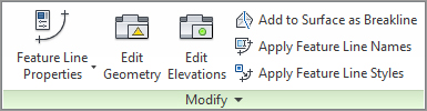
The Modify panel commands provide access to various properties of the feature line, the feature line style, and the feature line geometry as follows:
- The Feature Line Properties drop-down menu contains two commands. The first command, Feature Line Properties, is used to access various physical properties such as minimum and maximum grade. Only the name and style of the feature line can be modified on the Information tab, as shown in Figure 15-10. The second command, Edit Feature Line Style, is used to access various display characteristics such as color and linetype.
Figure 15-10: The Information tab of the Feature Line Properties dialog

- The Edit Geometry toggle opens the Edit Geometry panel on the Feature Line tab (see Figure 15-11). This panel will remain open until the Edit Geometry button is toggled off (it’s highlighted when toggled on).
- The Edit Elevations toggle opens the Edit Elevations panel on the Feature Line tab (see Figure 15-12). This panel will remain open until the Edit Elevations button is toggled off (it’s highlighted when toggled on).
Figure 15-12: The Edit Elevations panel on the Feature Line tab
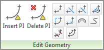
Figure 15-11: The Edit Geometry panel on the Feature Line tab

- The Add To Surface As Breakline tool allows you to select a feature line or feature lines to add to a surface as breaklines.
- The Apply Feature Line Names tool allows you to change a series of feature lines en masse based on a new naming template. This tool can be helpful when you want to rename a group or just assign names to feature line objects. This tool cannot be used on a feature line that is tied to an alignment and profile.
- The Apply Feature Line Styles tool allows you to change feature line objects and their respective styles en masse. Many users don’t apply styles to their feature line objects because the feature lines are found in grading drawings and not meant to be seen in construction documents. But if you need to make a global change, you can.
Once the Feature Line tab has been activated, the Quick Profile tool is available on the Launch Pad panel. The Quick Profile tool generates a temporary profile of the feature line based on user parameters found in the Create Quick Profiles dialog (Figure 15-13).
Figure 15-13: The Create Quick Profiles dialog
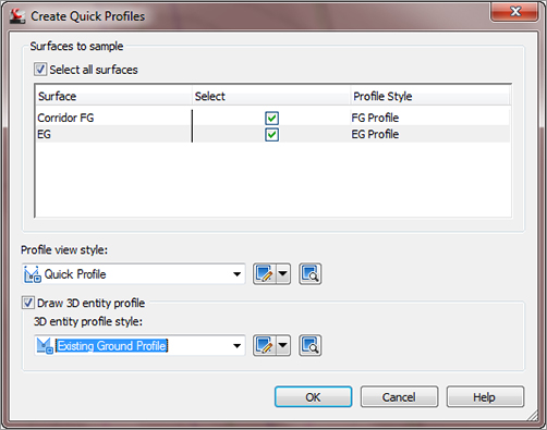
A few notes on this operation:
- Civil 3D creates a phantom alignment that will not display in Prospector as the basis for a quick profile. A unique alignment number is assigned to this alignment, so your number might be different from that shown.
- A closed feature line will generate a parcel when the quick profile is executed.
- Panorama will display a message to tell you that a profile view has been generated. You can close Panorama or move the Panorama palette out of the way if necessary.
Now that you’ve created a couple of feature lines, you’ll edit and manipulate them some more.
Editing Feature Line Horizontal Information
Creating feature lines is straightforward. The Edit Geometry and Edit Elevations tools make them considerably more powerful than a standard 3D polyline. The Edit Geometry and Edit Elevations tools can be accessed by changing to the Modify tab and choosing Feature Line, or simply by selecting an existing feature line. Both tools are found on the Modify panel of the Feature Line tab. The Edit Geometry functions are examined in this section, and the Edit Elevations functions are described in the next section.
Grading revisions often require adding PIs, breaking apart feature lines, trimming, and performing other planar operations without destroying the vertical information. To access the commands for editing feature line horizontal information, first change to the Modify tab and choose Feature Line from the Design panel. Then choose Edit Geometry from the Modify panel to open the Edit Geometry panel. The first two tools are designed to manipulate the PI points that make up a feature line:

- The Insert PI tool allows you to insert a new PI, controlling both the horizontal and vertical design.

- The Delete PI tool removes a PI. The feature line will mend the adjoining segments if possible, attempting to maintain similar geometry.
The next few tools act like their AutoCAD counterparts, but understand that elevations are involved and add PIs accordingly:
- The Break tool operates much like the AutoCAD Break command, allowing two objects or segments to be created from one. Additionally, if a feature line is part of a surface definition, both new feature lines are added to the surface definition to maintain integrity. Elevations at the new PIs are assigned on the basis of an interpolated elevation.
- The Trim tool acts like the AutoCAD Trim command, adding a new end PI on the basis of an interpolated elevation.
- The Join tool creates one feature line from two, making editing and control easier.
- The Reverse tool changes the direction of a feature line.
- The Edit Curve tool allows you to modify the radius that has been applied to a feature line object.
- The Fillet tool inserts a curve at PIs along a feature line and will connect feature lines sharing a common PI that are not actually connected.
The last few tools refine feature lines, making them easier to manipulate and use in surface building:
- The Fit Curve tool analyzes a number of elevation points and attempts to define a working arc through them all. This tool is often used when the corridor utilities are used to generate feature lines. These derived feature lines can have a large number of unnecessary PIs in curved areas.
- The Smooth tool turns a series of disjointed feature line segments and creates a best-fit curve. This tool is great for creating streamlines or other natural terrain features that are known to curve, but there’s often not enough data to fully draw them that way.
- The Weed tool allows the user to remove elevation points and PIs on the basis of various criteria. This is great for cleaning up corridor-generated feature lines as well.
- As discussed in detail earlier, the Stepped Offset tool allows offsetting in a horizontal and vertical manner, making it easy to create stepped features such as stairs or curbs.
By using these controls, it’s easier to manipulate the design elements of a typical site while still using feature lines for surface design. In this exercise, you manipulate a number of feature lines that were created by corridor operations:
1. Open the HorizontalFeatureLineEdits.dwg file. This drawing is a continuation of the SteppedOffset.dwg file but has been populated with some more feature lines.
2. Pick the lower horizontal feature line (which is the Syrah Way road), as shown in Figure 15-14.
Figure 15-14: Picking the lower feature line on Syrah Way
3. Choose Edit Geometry from the Modify panel to enable the Edit Geometry panel.
4. Click the Break tool. Pick the lower feature line again.
5. Enter F↵ to pick the first point of the break. When prompted to Specify second break point or [First point]:, enter F↵.
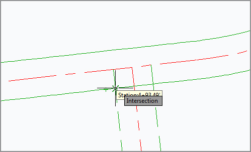
6. Using an Intersection osnap, pick the intersection of the horizontal feature line and the vertical feature line, as shown in Figure 15-15.
Figure 15-15: Using the Intersection object snap to select a point
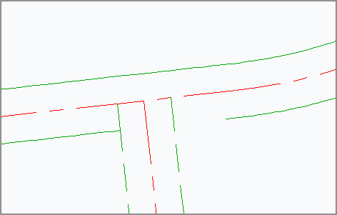
7. Using a Nearest osnap, pick a point on the horizontal feature line, leaving a gap, as shown in Figure 15-16.
Figure 15-16: The feature line after executing the Break command
8. Pick the two vertical feature lines to activate grips on both lines. Notice the large number of grips. Press Esc.
9. Pick the left horizontal feature line that was previously broken and click the Weed tool on the Edit Geometry panel to display the Weed Vertices dialog.
10. Pick the feature line again when you see the prompt Select a feature line, 3d polyline or [Multiple/Partial]:. The Weed Vertices dialog will be displayed.
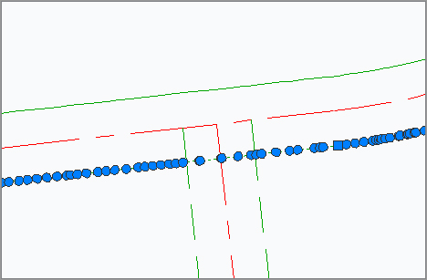
11. Watch the glyphs on the feature line and notice the number of vertices that will be removed from the feature line. Additionally, the glyphs on the feature line itself will change from green to red to reflect nodes that will be removed under the current setting, as shown in Figure 15-17. Click OK to complete the command and dismiss the Weed Vertices dialog.
Figure 15-17: Feature lines to be weeded

12. Using a standard AutoCAD Extend command, extend the horizontal feature lines that contain a gap.
13. Pick the left horizontal feature line and click the Trim tool from the Edit Geometry panel. A standard AutoCAD trim will not work in this case. Pick the horizontal feature line as the cutting edge and press ↵. Choose the vertical feature line when you see the prompt Select objects to trim:. Press ↵ to complete the command and review the results (see Figure 15-18). Press Esc.
Figure 15-18: The left horizontal feature line trimmed

14. Select the left horizontal feature line and click the Join tool on the Edit Geometry panel.
15. Select the left vertical feature line and press ↵. Notice the grips and that the two feature lines have been joined.
16. Select the Fillet tool. Enter R↵ at the command line to adjust the radius value. Enter 15↵ (4.57 m) to update the radius value.
17. Move your cursor toward the intersection of feature lines B and D until the glyph appears. Pick near the glyph to fillet the two feature lines.
18. Click the Edit Curve tool from the Edit Geometry panel and pick the curve when you see the prompt Select feature line curve to edit or [Delete]:. The Edit Feature Line Curve dialog opens, as shown in Figure 15-19.
Figure 15-19: The Edit Feature Line Curve dialog

19. Enter a Radius value of 34 (10.36 m), as shown in Figure 15-20, and click OK to close the dialog. Press ↵ to exit the command.
Figure 15-20: Filleted feature lines

When modifying the radius of a feature line curve, it’s important to remember that you must have enough tangent feature line on either side of the curve segment to make a curve fit, or the program will not make the change. In that case, tweak the feature line on either side of the arc until there is a mathematical solution. Sometimes it is necessary to use the Weed Vertices tool to remove vertices and create enough room to fillet feature lines. In some cases, it may be necessary to plan ahead when creating feature lines to ensure that vertices will not be placed too closely together.
Editing Feature Line Elevation Information
To access the commands for editing feature line elevation information, first change to the Modify tab and choose Feature Line from the Design panel. Then choose Edit Elevations from the Modify panel to open the Edit Elevations panel. Moving across the panel, you find the following tools for modifying or assigning elevations to feature lines:

- The Elevation Editor tool activates a palette in Panorama to display station, elevation, length, and grade information about the feature line selected. Feature lines, survey figures, and parcel lines can be edited using this tool.

- The Insert Elevation Point tool inserts an elevation point at the point selected. Note that this point can control only elevation information; it does not act as a horizontal control point. Feature lines, survey figures, parcel lines, and 3D polylines can be edited using this tool.
- The Delete Elevation Point tool deletes the selected elevation point; the points on either side then become connected linearly on the basis of their current elevations. Feature lines, survey figures, parcel lines, and 3D polylines can be edited using this tool.

- The Quick Elevation Edit tool allows you to use onscreen cues to set elevations and slopes quickly between PIs on any feature lines or parcels in your drawing.
- The Edit Elevations tool steps through the selected feature line, much like working through a polyline edit at the command line. Feature lines, survey figures, parcel lines, and 3D polylines can be edited using this tool.
- The Set Grade/Slope Between Points tool sets a continuous slope along the feature line between selected points. Feature lines, survey figures, parcel lines, and 3D polylines can be edited using this tool.
- The Insert High/Low Elevation Point tool places a new elevation point on the basis of two picked points and the forward and backward slopes. This calculated point is simply placed at the intersection of two vertical slopes. Feature lines, survey figures, parcel lines, and 3D polylines can be edited using this tool.
- The Raise/Lower By Reference tool allows you to adjust a feature line elevation based on a given slope from another location. Feature lines, survey figures, parcel lines, and 3D polylines can be edited using this tool.
- The Set Elevation By Reference tool sets the elevation of a selected point along the feature line by picking a reference point, and then establishing a relationship to the selected feature line point. This relationship isn’t dynamic! This button also acts as a flyout for the next three tools. Feature lines, survey figures, parcel lines, and 3D polylines can be edited using this tool.
- The Adjacent Elevations By Reference tool allows you to adjust the elevation on a feature line by coming at a given slope or delta from another point or feature line point. Feature lines, survey figures, parcel lines, and 3D polylines can be edited using this tool.
- The Grade Extension By Reference tool allows you to apply the same grades to different feature lines across a gap. For example, you might use this tool along the back of curbs at locations such as driveways or intersections. Feature lines, survey figures, parcel lines, and 3D polylines can be edited using this tool.
- The Elevations From Surface tool sets the elevation at each PI and elevation point on the basis of the selected surface. It will optionally add elevation points at any point where the feature line crosses a surface TIN line. Feature lines, survey figures, parcel lines, and 3D polylines can be edited using this tool.
- The Raise/Lower tool simply moves the entire feature line in the z direction by an amount entered at the command line. Feature lines, survey figures, parcel lines, and 3D polylines can be edited using this tool.
Quite a few tools are available to modify and manipulate feature lines. You won’t use all of the tools, but at least you’ll have some concept of what is available. The next exercises give you a look at a few of them. In this first exercise, you’ll make manual edits to set the grade of a feature line segment:
1. Open the EditingFeatureLineElevations.dwg file.
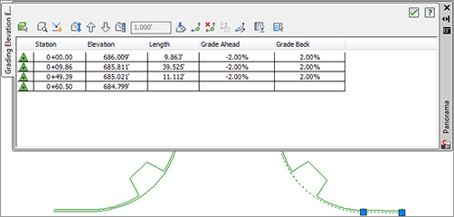
2. Select one of the vertical feature lines. The Grading Elevation Editor in Panorama will open, as shown in Figure 15-21.
Figure 15-21: The Grading Elevation Editor
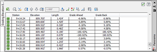
3. Click in the Grade Ahead column for the first PI. It’s hard to see in the images, but as a row is selected in the Grading Elevation Editor, the PI or the elevation point that was selected will be highlighted on the screen with a small glyph.
4. You can use the Editor to make changes to the Station, Elevation, Length, Grade Ahead, and Grade Back. The exception is that you cannot edit stationing for primary geometry points, as indicated by the triangle glyph in the Grading Elevation Editor.
5. Click the green check mark in the upper-right corner to dismiss the Panorama. We will look at the Grading Elevation Editor more in-depth next.
Using the Grading Elevation Editor is the most basic way to manipulate elevation information.
The Grading Elevation Editor
We have discussed this very important editor and the plethora of tools available inside it. Many of the tools may seem redundant from the Feature Line Edit Elevations tools, but they are placed here for ease of use. Refer back to Figure 15-21 for a graphical display of the Grading Elevation Editor panorama.
- Clicking the Select tool allows you to select the object for editing.
- The Zoom To tool will do exactly as it says. If you have a station highlighted in the panorama and select the Zoom To tool, your plan view will be zoomed to that elevation point.
- The Quick Profile tool will create a quick profile based on the feature line selected. The Create Quick Profiles dialog will open and allow you to select what surface(s) you wish to display as well as what profile view style and 3D entity profile you want.
- Clicking the Raise/Lower tool will activate the Set Increment text box. This allows you to raise or lower selected elevation points, or if no elevation points are selected, it will raise or lower the entire feature line elevation points by the amount displayed in the text box.
- The Raise Incrementally/Lower Incrementally tools will raise or lower the elevation point or points by the amount listed in the Increment text box.
- The Set Increment tool works in tandem with the text box. You can type in a value that will be used by other tools for raising or lowering elevation point or points.
- The Flatten Grade Or Elevations tool will make all selected elevation points the value of the first selected point, or if no points are selected, the value of the first entry in the cells. When this tool is selected, the Flatten dialog will open asking if you want to flatten by constant elevation or grade.
- The Insert Elevation Point will let you select a spot on the feature line, and will create an intermediate elevation point. The Insert PVI dialog box will open, allowing you to fine-tune the station and enter an elevation.
- The Delete Elevation Point will delete a point or points that are highlighted in the editor. Note that this tool will only allow you to delete intermediate points.
- Clicking the Elevations For Surface tool will open the Select Surface dialog if there are multiple surfaces to choose from. If you have an elevation point or points selected, it will only affect those points, or if nothing is selected it will use all elevation points and drape them onto the selected surface.
- The Reverse direction tool will do exactly as it says; it will reverse the direction of the feature line.
- The Show Grade Breaks Only tool is a toggle (click, it’s on and click, it’s off) that will display only grade breaks on a feature line.
- The Unselect All Rows tool does exactly as it says; it will deselect any rows that have been highlighted for editing.
More Feature Line Editing Tools
Some of the relative elevation tools are a bit harder to understand, so you’ll look at them in our next exercise and see how they function in some basic scenarios:
1. Open the EditingRelativeFeatureLineElevations.dwg file. This drawing contains a sample layout with some curb and gutter work.
2. Zoom to the ramp shown on the left-hand side of the intersection.
3. Select the feature line describing the ramp. Select Edit Elevations from the Modify panel to display the Edit Elevations panel if it isn’t displayed already. Select Elevation Editor. The Panorama appears. Notice that the entire feature line is at elevation 0.000′ (0.000 m). Click the green check mark in the upper right to close the Panorama. Press Esc to cancel the grips.
4. Select the feature line representing the flowline of the curb and gutter area.
5. Select the Adjacent Elevations By Reference tool. Civil 3D will prompt you to select the object to edit. You will edit the elevations along the feature line describing the ramp area.
6. Click the feature line describing the ramp area and Civil 3D will display a number of glyphs and lines to represent what points along the flowline it is using to establish elevations from, and it will prompt you for the elevation difference (you could also use a grade or slope).
7. Enter 0.5 (0.15 m) at the command line and press ↵ to update the ramp elevations. Press ↵ again to exit the command, and press Esc to cancel grips.
8. Select the feature line describing the ramp. Select Elevation Editor, and the Panorama appears. Notice that the PIs now each have an elevation, as shown in Figure 15-22.
Figure 15-22: Completed editing of the curb ramp feature line

9. Click the green check mark in the upper right of the Panorama to dismiss it. Leave this drawing open.
Next, you’ll need to extend the grade along the line representing the flowline of the curb and gutter area on the left of the screen to determine the elevation to the south of your intersection on the right of the screen. You’ll use the Grade Extension By Reference tool in the following exercise to accomplish this:
1. This exercise is a continuation of the previous exercise. Click the feature line representing the flowline of the curb and gutter area on the left side of the drawing.
2. Select the Grade Extension By Reference tool and select the flowline again when you see the prompt Select reference segment: (see Figure 15-23). This tool will evaluate the feature line as if it were three separate components (two lines and an arc). Because you are extending the grade of the flowline to the east and across the intersection, it is important to select the tangent segment, as shown in Figure 15-23.
Figure 15-23: Selecting the flowline of the curb and gutter section

3. At the Select object to edit: prompt, select the line representing the flowline of the curb and gutter area to the right of your screen, as shown in Figure 15-24.
Figure 15-24: Selecting the flowline at the left side of the tangent segment
4. At the Specify point: prompt, pick the PI at the left side of the tangent, as shown in Figure 15-25.
Figure 15-25: Selecting the PI at the left side of the tangent segment representing the flowline of the curb and gutter section

5. At the Specify grade or [Slope/Elevation/Difference] <2.21>: prompt, press ↵ to accept the default value of 2.21 (this is the grade of the flowline of the curb and gutter section to the left). Press ↵ to end the command, and press Esc to cancel grips.
6. Select the feature line representing the flowline of the curb and gutter section to the right of your screen to enable grips.
7. Move your cursor over the top of the PI, as shown in Figure 15-26, but do not click. Your cursor will automatically snap to the grip, and the grip will change color. Notice that the elevation of the PI is displayed on the status bar, as shown in Figure 15-26. This is a quick way to check elevations of vertices when modeling terrain. If your coordinates are not displayed, type the AutoCAD command COORDS, and set the value to 1 to display them. Leave this drawing open for the next exercise.
Figure 15-26: The x-, y-, and z-coordinates of the PI displayed on the status bar

With the elevation of a single point determined, the grade of the feature line representing the curb and gutter section can be modified to ensure positive water flow. In the following exercise, you’ll use the Set Grade/Slope Between Points tool to modify the grade of the feature line:
1. This exercise is a continuation of the previous exercise. Select the feature line representing the flowline of the curb and gutter section to the right of your screen. Select the Set Grade/Slope Between Points tool from the Edit Elevations panel.
2. When you see the prompt Specify the start point:, pick the PI as shown previously in Figure 15-25. The elevation of this point has been established and will be used as the basis for grading the entire feature line.
3. At the Specify elevation <685.021>: prompt, press ↵ to accept the default value. This is the current elevation of the PI as established earlier.
4. When you see the prompt Specify the end point:, pick the PI as shown in Figure 15-27.
Figure 15-27: Specifying the PI to establish the elevation at the flowline of the curb and gutter section
5. At the Specify grade or [Slope/Elevation/Difference]: prompt, type 2 and press ↵ to set the grade between the points at 2 percent. Do not exit the command.
6. When you see the prompt Select object:, select the feature line representing the flowline of the curb and gutter section to the right again.
7. When you see the prompt Specify the start point:, pick the PI (shown earlier in Figure 15-26) again.
8. At the Specify elevation <685.021> prompt, press ↵ to accept the default value. This is the current elevation of the PI as established earlier.
9. When you see the prompt Specify the end point:, pick the PI at the far bottom right along the feature line currently being edited.
10. At the Specify grade or [Slope/Elevation/Difference]: prompt, type -2 and press ↵ to set the grade between the points at negative 2 percent. Press ↵ to exit the command but do not cancel grips.
11. Select the Elevation Editor tool from the Edit Elevations panel to open Panorama. Notice the values in both the Grade Ahead and Grade Back columns, as shown in Figure 15-28.
Figure 15-28: The grade of the feature line set to 2 percent
The possibilities are endless. In using feature lines to model proposed features, you are limited only by your creative approach. You’ve seen many of the tools in action, so you can now put a few more of them together and grade your pond.
Draining the Pond
You need to use a combination of feature line tools and options to pull your pond together, and get the most flexibility should you need to update the bottom area or manipulate the pond’s general shape. Here is the method that was used when this pond was designed:
1. Open the PondDrainageDesign.dwg file. The engineer gave us a bit more information about the pond design, as shown here:

2. Click the pond basin outline and click the Insert Elevation Point tool.
3. Use the Center osnap to insert the elevation points in the center of each circle. Enter 779.5 (237.59 m) as the elevation of each inflow, and accept the default elevation at the outflow. (You will change the elevation at the outflow in a moment.) Press ↵ to exit the command, and press Esc to cancel grips.
4. Draw a polyline, similar to the one shown here, from the northwestern inflow point, through the outflow, and snap to the endpoint of the drainage channel feature line. Be sure to place a PI at the center of the circle designating the outflow point. This polyline will be the layout for the pilot channel.
5. Change to the Home tab and choose Feature Line ⇒ Create Feature Lines From Objects from the Create Design panel. Pick the polyline just drawn and press ↵. The Create Feature Lines dialog appears.
6. Click OK to complete the conversion, making sure that the Assign Elevations check box is left unchecked. Because this feature line was created in the same site as the bottom of the pond, the elevation of the PI at the southernmost inflow will reset to match the elevation of the endpoint of the pilot channel.
7. Select the feature line representing the pilot channel and pick the Fillet tool from the Edit Geometry panel.
8. Enter R↵, and enter 25↵ (7.62 m) for the radius.
9. Enter A↵ to fillet all PIs.
10. Press ↵ to exit the Fillet command.
11. Select the feature line representing to pilot channel. Click the Set Grade/Slope Between Points tool on the Edit Elevations panel.
12. Pick the PI at the inflow.
13. Enter 779.5↵ (237.59 m) to set this elevation.
14. Pick the other end of the feature line, as shown here. All the PIs will highlight, and Civil 3D will display the total length, elevation difference, and average slope at the command line.

15. Press ↵ again to accept the grade as shown. This completes a linear slope from one end of the feature line to the other, ensuring drainage through the pond and outfall structure.
16. Press ↵ to exit the command. Press Esc to cancel grips.
17. Select the bottom of the pond and choose the Elevation Editor tool to open the Grading Elevation Editor in Panorama.
18. Click in the Station cells in the Grading Elevation Editor to highlight and ascertain the elevation at the outfall, as shown here. In this case, the elevation is 775.471′ (236.36 m). Some minor variation might occur depending on your pick points and the length of your pilot channel. Notice also that the icon for this point in the Panorama display is a white triangle, indicating that this point is a point derived from a feature line intersection. This is called a phantom PI.

19. Click the Insert Elevation Point tool in the Panorama.
20. Using an intersection snap, set a new elevation point at the intersection of the pilot channel and the flowline. The Insert PVI dialog opens. Enter an elevation of 775.471′ (236.36 m) or the elevation you ascertained earlier in the Elevation text box. This has to be added after the pilot channel has been created because the fillet process would tweak the location. Click OK to exit the Insert PVI dialog.
21. Close Panorama. A round grip is displayed at this new elevation point.
22. Select the pond bottom and click the Quick Elevation Edit tool on the Edit Elevations panel. Move your cursor over the PI at the inflow that we created the feature line from. Pick the PI. Enter 782 (238.35 m) and press ↵ twice to exit the command.
23. Click the Set Grade/Slope Between Points tool on the Edit Elevations panel.
24. Move your cursor over the PI selected in step 22 once again and pick it. Press ↵ to accept the default elevation set previously as 782 (238.35 m).
25. Pick the PI at the outflow. Enter the elevation of 775.471 (236.36 m).
26. Press ↵ to accept the grade. This sets the elevations between the one infall and the outfall PIs to all fall at the same grade.
27. Repeat steps 22–26 for the PI on the other infall (located on the northeast side of the pond) and the outfall. They will set the elevations between the other infall and the outfall to a constant slope.
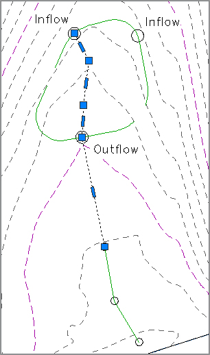
The entire outline of the pond bottom is graded except the area between the two inflows, as shown here:
Because you want to avoid a low spot, you’ll now force a high point:
1. Click the Insert High/Low Elevation Point tool.
2. Pick the PI near the northwestern inflow.
3. Pick the PI near the northeastern inflow as the endpoint. Enter 1.0↵ as the grade ahead.
4. Enter 1.0↵ as the grade behind. A new elevation point will be created, as shown here:
5. Trim the feature line from inside the bottom of the pond using the Feature Line Trim tool.
By using all the tools in the Feature Lines toolbar, you can quickly grade elements of your design and pull them together. If you have difficulty getting all the elevations in this exercise to set as they should, slow down, and make sure you are moving your mouse in the right direction when setting the grades by slope. It’s easy to get the calculation performed around the other direction—that is, clockwise versus counterclockwise. This procedure seemed to involve a lot of steps, but it takes less than a minute in practice.
There are roughly 25 ways to modify feature lines using both the Edit Geometry and Edit Elevations panels. Take a few minutes and experiment with them to understand the options and tools available for these essential grading elements. By manipulating the various pieces of the feature line collection, it’s easier than ever to create dynamic modeling tools that match the designer’s intent.
Labeling Feature Lines
Though it’s not common, feature lines can be stylized to reflect particular uses, and labels can be applied to help a reviewer understand the nature of the object being shown. In the next couple of exercises, you’ll label a few critical points on your pond design to help you better understand the drainage patterns.
Feature Line Labels
Feature lines do not have their own unique label styles but instead share with general lines and arcs. You can learn more about styles in Chapter 19, “Styles.” The templates that ship with Civil 3D contain styles for labeling segment slopes, so you’ll label the critical slopes in the following exercise:
1. Open the Labeling Feature Lines.dwg file if you closed it.
2. Change to the Annotate panel and choose Add Labels from the Labels & Tables panel.
3. In the Add Labels dialog, choose Line And Curve from the Feature drop-down, and then change Line Label Style to Grade Only and Curve Label Style to Radius Only, as shown in Figure 15-29.
Figure 15-29: Adding feature line grade labels

4. Click Add.
5. Pick a few points along the Pilot Channel feature line tangents to create labels, as shown in Figure 15-29.
Although it would be convenient to label the feature line elevations as well, there’s no simple method for doing so. In practice, you would want to label the surface that contains the feature line as a component.