
Once a linear feature line is created, there are two main uses. One is to incorporate the feature line itself directly into a surface object as a breakline; the other is to create a grading object (referred to hereafter as simply a grading or gradings) using the feature line as a baseline. A grading consists of some baseline with elevation information, and a criteria set for projecting outward from that baseline based on distance, slope, or other criteria. These criteria sets can be defined and stored in grading criteria sets for ease of management. Finally, gradings can be stylized to reflect plan production practices or convey information such as cut or fill.
In this section, you’ll use a number of methods to create gradings, edit those gradings, stylize the gradings, and finally convert the grading group into a surface.
Creating Gradings
Let’s look at grading the pond as designed. In this section, you’ll look at grading groups and then create the individual gradings within the group. Grading groups act as a collection mechanism for individual gradings and let Civil 3D understand the daisy chain of individual gradings that are related and act in sync with each other.
One thing to be careful of when working with gradings is that they are part of a site. Any feature line within that same site will react with the feature lines created by the grading. For that reason, the exercise drawing has a second site called Pond Grading to be used for just the pond grading.
1. Open the GradingThePond.dwg file.
2. Pick the pond bottom.
3. Right-click and choose Move To Site. The Move To Site dialog appears.
4. Choose Pond Grading from the Destination Site drop-down list. Click OK. This will avoid interaction between the pond banks and the pilot channel you laid out earlier.
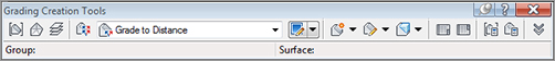
5. With the feature line still selected, choose Grading Creation Tools from the Launch Pad panel. The Grading Creation Tools toolbar, shown in Figure 15-30, appears. This toolbar is similar to the one used in pipe networks. The left section is focused on settings, the middle on creation, and the right on editing.
Figure 15-30: The Grading Creation Tools toolbar
6. Click the Set The Grading Group tool to the far left of the toolbar to display the Site dialog. Choose the Pond site and click OK. The Create Grading Group dialog is displayed.
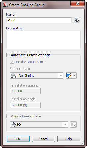
7. Enter Pond in the Name text box, as shown in Figure 15-31, and click OK. You’ll revisit the surface creation options in a bit.
Figure 15-31: Assign the name Pond in the Create Grading Group dialog.
8. Click the Select Target Surface tool located next to the Select Grading Group tool. Select the EG surface.
9. Click the Select A Criteria Set tool to display the Select A Criteria Set dialog.
10. Select Pond Grading from the drop-down list and click OK to close the dialog.
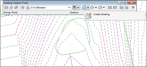
11. Click the Create Grading tool on the Grading Creation Tools toolbar, or click the down arrow next to the Create Grading tool and select Create Grading, as shown in Figure 15-32.
Figure 15-32: Creating a grading using the 3:1 To Elevation criteria
12. Pick the pond outline. If you get a dialog asking you to weed the feature line, select the Weed Feature Line option and click OK at the next dialog.
13. Pick a point on the outside of the pond to indicate the direction of the grading projections.
14. Press ↵ to apply the grading to the entire length of the pond outline.
15. Enter 784↵ (238.96 m) at the command line as the target elevation. The first grading is complete. The lines onscreen are part of the Grading style.
16. In the Select A Grading Criteria drop-down list on the Grading Creation Tools toolbar, select Flat Ledge.
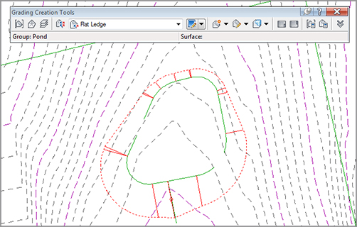
17. Pick the upper boundary of the grading made in step 16, as shown in Figure 15-33.
Figure 15-33: Creating a daisy chain of gradings
18. Press ↵ to apply to the whole length.
19. Enter 10↵ (3.05 m) for the target distance to build the safety ledge.
20. In the Select A Grading Criteria drop-down list on the Grading Creation Tools toolbar, select 3:1 To Surface.
21. Pick the outer edge of the safety ledge just created.
22. Press ↵ to apply to the whole length. Press ↵ to exit the command. Your drawing should look similar to Figure 15-34.
Figure 15-34: Complete pond interior grading
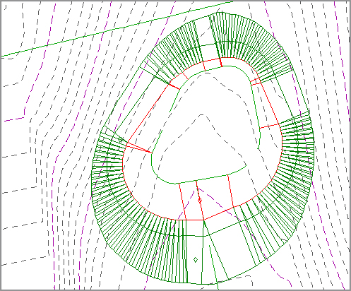
Each piece of this pond is tied to the next, creating a dynamic model of your pond design on the basis of the designer’s intent. What if that intent changes? The next section describes editing the various gradings.
Editing Gradings
Once you’ve created a grading, you often need to make changes. A change can be as simple as changing the slope or changing the geometric layout. In this exercise, you’ll make a simple change, but the concept applies to all the gradings you’ve created in your pond. Because the grading criteria were originally locked to make life easier, you’ll now unlock them before modifying the daylight portion of the pond:
1. Open the EditingGrading.dwg file.
2. Pick one of the projection lines or the small diamond on the outside of the pond.
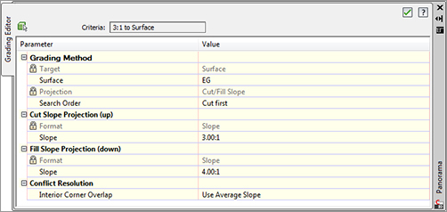
3. Choose the Grading Editor tool from the Modify panel. The Grading Editor in Panorama appears.
4. Enter 4:1 for a Fill Slope Projection, as shown in Figure 15-35.
Figure 15-35: Editing the Fill Slope value
5. Close Panorama. Your display should look like Figure 15-36. (Compare this to Figure 15-34 if you’d like to see the difference.)
Figure 15-36: Completed grading edit
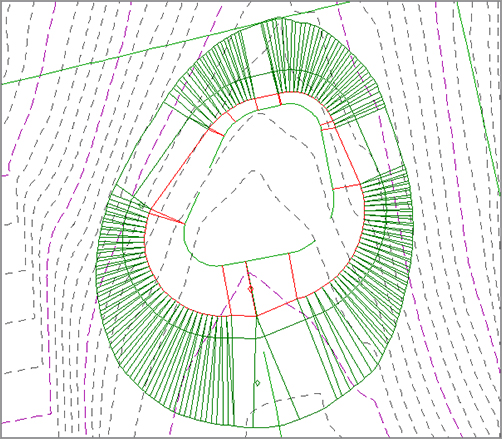
Editing any aspect of the grading will reflect instantly, and if other gradings within the group are dependent on the results of the modified grading, they will recalculate as well.
Creating Surfaces from Grading Groups
Grading groups work well for creating the model, but you have to use a TIN surface to go much further with them. In this section, you’ll look at the conversion process, and then use the built-in tools to understand the impact of your grading group on site volumes.
1. Open the CreatingGradingSurfaces.dwg file.
2. Pick one of the diamonds in the grading group.
3. Select the Grading Group Properties tool from the Modify panel to display the Grading Group Properties dialog.
4. Switch to the Information tab if needed. Check the box for Automatic Surface Creation.
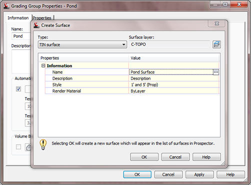
5. In the Create Surface dialog that appears, enter Pond Surface in the Name field.
6. Click in the Style field, and then click the ellipsis button. The Select Surface Style dialog appears. Select 1′ And 5′ (Prop) from the drop-down list in the selection box, as shown in Figure 15-37. Click OK twice to return to the Grading Group Properties dialog.
Figure 15-37: Creating a grading group surface
7. In the Grading Group Properties dialog, check the Volume Base Surface option and select the EG surface to perform a volume calculation. Click OK to dismiss the dialog.
You’re going through this process now because you didn’t turn on the Automatic Surface Creation option when you created the grading group. If you’re performing straightforward gradings, that option can be a bit faster and simpler. There are two options available when creating a surface from a grading group. They both control the creation of projection lines in a curved area:
- The Tessellation Spacing value controls how frequently along an arced feature line TIN points are created and projection lines are calculated. A TIN surface cannot contain any true curves the way a feature line can because it is built from triangles. The default values typically work for site mass grading, but might not be low enough to work with things such as parking lot islands where the 10′ (3.05 m) value would result in too little detail.
- The Tessellation Angle value is the degree measured between outside corners in a feature line. Corners with no curve segment have to have a number of projections swung in a radial pattern to calculate the TIN lines in the surface. The tessellation angle is the angular distance between these radial projections. The typical values work most of the time, but in large grading surfaces, a larger value might be acceptable, lowering the amount of data to calculate without significantly altering the final surface created.
There is one small problem with this surface. If you examine the bottom of the pond, you’ll notice there are no contours running through this area. If you move your mouse to the middle, you also won’t have any Tooltip elevation as there is no surface data in the bottom of the pond. To fix that (and make the volumes accurate), you need a grading infill.
8. From the Modify tab and Modify panel, select Create Grading Infill.
9. Civil 3D will prompt you at the command line to select an infill area. Hover your cursor over the middle of the pond and the pond feature line created earlier will be highlighted, indicating a valid area for infill.
10. Click once to create the infill, and press ↵ to apply. Civil 3D will calculate, and Panorama may appear. Dismiss it. You should now have some contours running through the pond base area, as shown in Figure 15-38.
Figure 15-38: The pond after applying an infill grading

11. Zoom in if needed and pick one of the grading diamonds again to select one of the gradings. Make sure you grab one of the gradings and not the surface contours that are being drawn on top of them.
12. Select Grading Group Properties from the Modify panel to open the Grading Group Properties dialog.
13. Switch to the Properties tab to display the Volume information for the pond, as shown in Figure 15-39. This tab also allows you to review the criteria and styles being used in the grading group.
Figure 15-39: Reviewing the grading group volumes
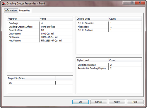
This new surface is listed in Prospector and is based on the gradings created. A change to the gradings would affect the grading group, which would, in turn, affect the surface and these volumes. In the following exercise, you’ll pull it all together:
1. Open the CreatingCompositeSurfaces.dwg file.
2. Right-click Surfaces in Prospector and select Create Surface.
3. In the Create Surface dialog, enter Composite in the Name text box. Click in the Style field, and then click the ellipsis to open the Select Surface Style dialog. Select the Contours 2′ And 10′ (Prop) option from the drop-down list box, and click OK.
4. Click OK to dismiss the Create Surface dialog and create the surface in Prospector.
5. In Prospector, expand the Surfaces ⇒ Composite ⇒ Definition branches.
6. Right-click Edits and select Paste Surface. The Select Surface To Paste dialog shown in Figure 15-40 appears.
Figure 15-40: Pasting surfaces together
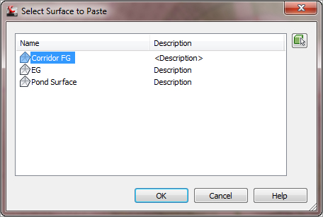
7. Select EG from the list and click OK. Dismiss Panorama if it appears.
8. Right-click Edits again and select Paste Surface one more time.
9. Select Pond Surface and click OK.
10. Change the Corridor FG, EG, and Pond Surface display settings to No Display. The drawing should look like Figure 15-41.
Figure 15-41: Completed composite surface

By creating a composite surface consisting of pasted-together surfaces, the TIN triangulation cleans up any gaps in the data, making contours that are continuous from the original grade, through the pond, and out the other side. With the grading group still being dynamic and editable, this composite surface reflects a dynamic grading solution that will update with any changes.