
Understanding Floor Modeling Methods
![]() Floors are likely to be one of the first sketch-based elements you will encounter in Revit. Many families in the default libraries are floor hosted, so you must first have a floor before placing such components. Consequently, these components will be deleted if the floor that hosts them is deleted. You can find a more detailed discussion on creating families in Chapter 15, “Family Editor,” but for now let's review the fundamental types of floors that can exist in a Revit project: a floor, a structural floor, a floor by face, and a pad.
Floors are likely to be one of the first sketch-based elements you will encounter in Revit. Many families in the default libraries are floor hosted, so you must first have a floor before placing such components. Consequently, these components will be deleted if the floor that hosts them is deleted. You can find a more detailed discussion on creating families in Chapter 15, “Family Editor,” but for now let's review the fundamental types of floors that can exist in a Revit project: a floor, a structural floor, a floor by face, and a pad.
Floor
The traditional floor object is a sketch-based element comprised of any number of material layers as defined by the user. The top of the floor object is its reference with respect to the level on which it was created. As such, changes to a floor's structure will affect its depth down and away from the level. You can start modeling floors with generic types, which are similar to generic walls containing a single layer, and then change the generic floors to more specific assemblies later in the development of your project. To do this, select one or more floors and choose a different wall type from the Type Selector in the Properties palette. You can also use the Match Type Properties tool located in the Clipboard panel of the Modify tab of the ribbon.
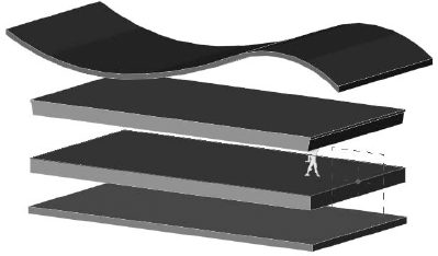
You can use floors in a variety of ways to meet the needs of a specific phase of design. In early phases, for example, you can create a floor type to represent the combined floor, structure, plenum, and ceiling assemblies of a building. Commonly referred to as the sandwich, a sample is shown in Figure 14.1.
FIGURE 14.1 A single floor type may be used to show the entire floor/ceiling sandwich in early design.
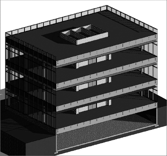
During intermediate phases of design, you can model ceilings so the floor types can include only the floor and a structural layer, as shown in Figure 14.2. Columns may be created, but more precise horizontal structural framing may not be modeled yet. The layer within the floor type represents an assumption of the maximum depth of structural framing.
In later phases approaching and including construction, floors should be modeled as close to actual conditions as possible. You should accommodate detailed finish conditions for floors as well as coordination with a resolved structural system. Accurate modeling of these conditions will help support consistent quantity takeoffs and interference detection. Figure 14.3 illustrates an example of a more accurate floor slab.
These floor assembly types are offered as suggestions for the sake of increased productivity. As such, they should be used with care, especially when performing quantity takeoffs for estimating. For example, the area of floor will be the only accurate value to be extracted from a floor sandwich model in early design, not a volumetric material takeoff. For more information on the use of models by others, we recommend referring to the AIA document E202 BIM Protocol Exhibit, which lists authorized uses of a model at various levels of development. You can download a sample of this document for free from www.aiacontractdocuments.org/bim.
FIGURE 14.2 This floor assembly includes an assumption for the depth of structural framing.

FIGURE 14.3 Floor assemblies for construction should be accurate and separate from structural framing.
![]() Real World Scenario: COLLABORATION AND THE OWNERSHIP OF FLOORS
Real World Scenario: COLLABORATION AND THE OWNERSHIP OF FLOORS
Whether or not you are working under an integrated project delivery (IPD) contract, the so-called ownership of floors should be carefully considered for the collaboration process between an architect and a structural engineer. Floors can be one of the most contentious elements of a building design because they can be simultaneously construed as architecture and structure.
The model element author (MEA) for floors should be discussed and clearly defined for each phase in your project BIM execution plan. Remember that element ownership can pass between the architect and the structural engineer when it is appropriate for a given phase. For example, the architect may choose to be the MEA for floors in schematic design, but pass ownership to the structural engineer in design development and construction documentation.
Structural Floor
The structural floor is similar to a traditional floor but has structural functionality, such as the ability to indicate span direction and to contain structural profiles. For example, you can specify a composite metal deck profile, which will display in sections and details generated within your project.
If you are working with a project file that has been upgraded from a previous version of Revit, the only way to create a new structural floor is to create a new one by going to the Home tab, locating the Build panel, and choosing Floor ![]() Structural Floor. Doing so creates a floor with the instance property called Structural (Figure 14.4). Note that because Structural is an instance property, any floor type can become a structural floor.
Structural Floor. Doing so creates a floor with the instance property called Structural (Figure 14.4). Note that because Structural is an instance property, any floor type can become a structural floor.
FIGURE 14.4 Structural parameter in a floor's instance properties

Once the Structural parameter check box has been selected for a floor, you can edit its type properties to add a structural decking layer. Let's create a new structural floor so you can explore how this is done:
- Open the file c14-Floors.rvt from the book's companion web page (www.sybex.com/go/masteringrevit2012), and activate the Level 3 floor plan.
- Go to the Home tab in the ribbon, and from the Build panel, select Floor
 Structural Floor.
 - In the Draw panel of the Modify | Create Floor Boundary ribbon, make sure your options are set to Boundary Lines with the Pick Walls tool, as shown in Figure 14.5.
FIGURE 14.5 Use Pick Walls mode to draw boundary lines.
- In the Options Bar, specify an offset of 0-3 [75 mm]. This setting will place the floor boundary just within the inner face of the curtain wall mullions because the location line of the curtain wall is at the center of the mullions that are 5 deep.
- Begin picking the exterior curtain walls by selecting one of the north-south–oriented walls first. Note that the first wall you pick will determine the span direction of the structural floor. You can change this at any time by picking the Span Direction tool from the Draw panel and then selecting one of the boundary lines in the floor sketch. Pick the remaining exterior walls to complete the floor boundary.
 Once you have finished defining the boundary lines of the floor, open the Properties palette by pressing Ctrl+1, typing PP, or clicking the Properties icon at the left end of the ribbon.
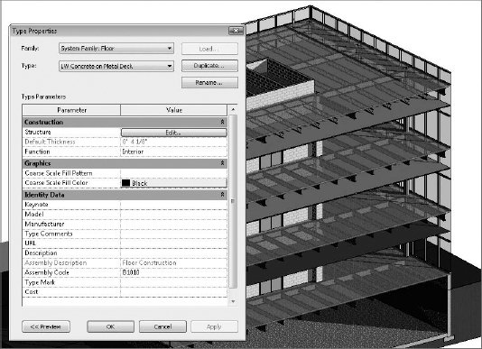
- Click Edit Type in the Properties palette. Select Generic - 12 as the active type and click Duplicate. Name the new type Structural Slab.
- In the Edit Type dialog box, click the Edit button in the Structure row to open the Edit Assembly dialog box.
- In the Edit Assembly dialog box, find the layer of the assembly that represented the generic floor you duplicated. This should be row 2. Change the material of this layer to Concrete – Cast-in-Place Concrete and change the thickness to 0-6.
- Select row 3 and click the Insert button. There should now be four layers. Select the new row 3 and set its function to Structural Deck [1]. Note the new Structural Deck Properties that appear below the layers, as shown in Figure 14.6.
FIGURE 14.6 Setting a layer's function to Structural Deck exposes additional options.
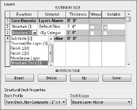
- The value for Deck Profile should default to Form Deck_Non-Composite: 2 × 6, but this depends on whether you have a structural deck profile loaded into your project.
If you don't have a structural deck profile loaded, finish the floor, select the Insert tab of the ribbon, and click Load Family. In your default Autodesk content library, find the Profiles folder and open the Structural subfolder. Pick an appropriate deck profile and click Open to load it. Select the Structural Slab floor and click Edit Type in the Properties palette to continue the exercise.
- Activate Wall Section 1, and you should see the completed slab at Level 3. Notice that you do not see the details of the structural decking when Detail Level is set to Coarse. If you activate the callout at Level 3 (Detail At Level 3), you will see the structural decking because the callout's Detail Level is set to Medium. This difference is illustrated in Figure 14.7.
FIGURE 14.7 Structural floor as represented in coarse detail level (left) and Medium detail level (right)

Floor By Face
This floor modeling method is used when you have generated an in-place mass or loaded a mass family. After you assign mass floors to a mass, you can use the floor by face method to assign and manage updates to floors, as shown in Figure 14.8. This type of floor modeling is discussed in greater detail in Chapter 9, “Advanced Modeling and Massing.”
FIGURE 14.8 The Floor By Face tool can be used to manage slabs in more complex building designs.

Pad
A pad is technically not a floor but has properties similar to a floor. What differentiates a pad is its ability to cut into a toposurface and define the lowest limits of a building's basement or cellar. If desired, the pad can be configured to represent a slab on grade, as shown in Figure 14.9.
FIGURE 14.9 A pad can be configured as a slab on grade for a basement.

Slab Edge
Slab Edge is a tool that allows you to create thickened portions of slabs typically located at the boundaries of floors. A slab edge type is composed of a profile family and a material assignment. It is important that the material assignment of the slab edge match that of the floor to which you will apply the slab edge in order to ensure proper joining of geometry. Let's explore the application of a slab edge to a floor at grade:
- Open the file c14-Design-Floor.rvt from the book's companion web page and activate the 3D view named Floors Only.
- Click the Home tab in the ribbon and select Floor Slab Edge from the Build panel. Note that this tool is also available from the Structure tab.
- If necessary, orbit the 3D view so that you can see the bottom of the lowest floor slab. Pick all four bottom edges of the floor slab at the level named Ground.
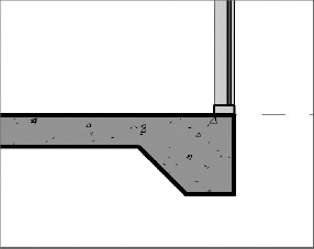
- Activate the view Section 1, and you will see the slab edge applied to and joined with the floor, as shown in Figure 14.10. Remember that the material in the slab edge type must match the material in the floor type properties for the geometry to join properly.
FIGURE 14.10 Thickened slab edge applied to the bottom of a floor
Creating a Custom Floor Edge
You can apply a great deal of flexibility to a floor assembly in early design. As we described earlier, you can create a floor for early design phases that accommodates the floor, structure, plenum, and ceiling in a single floor type. You can also apply a customized edge to this type of assembly for more creative soffit conditions at exterior walls, as shown in Figure 14.11.
FIGURE 14.11 Customized edge applied to a floor assembly in early design
Let's run through a short exercise so you can practice this skill:
- Open the file c14-Design-Floor.rvt from the book's companion web page and activate the view Section 1.
- Select the floor at Level 1 and open the Properties palette. Change the type to Design Floor Sandwich.
- Begin a new in-place component by going to the Home tab and selecting Component Model In-Place from the Build panel.
- Set the Family Category to Floors and specify the name as Floor Edge-L1.
Notice that you are now in Family Editing mode, and the ribbon will have different tabs and panels.
- Click the Home tab and select Void Forms Void Sweep from the Forms panel.
- Click the Pick Path tool from the Sweep panel and choose all four top edges at the perimeter of the floor at Level 1. You can activate the 3D view Floors Only to complete the picking of all four edges, as shown in Figure 14.12.
FIGURE 14.12 Pick edges of the void sweep in a 3D view.
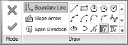
 Click the Finish Edit Mode icon in the Mode panel when all four edges of the floor have been picked.
- Open the Properties palette if it isn't already visible.
Note that you might need to reactivate the Select Profile mode if the Properties palette only lists Family: Floors. To do this, click the Modify | Sweep tab in the ribbon and click Select Profile in the Sweep panel.
- In the Profile parameter, select SD Sandwich Edge : 36 w 6 Slab from the drop-down list, as shown in Figure 14.13.
FIGURE 14.13 Select a loaded profile family for the void sweep.

Note that the SD Sandwich Edge profile has been preloaded for the convenience of this exercise. If you would like to explore how this profile was created, expand the Families tree in the Project Browser and find Profiles
SD Sandwich Edge. Right-click it and choose Edit from the context menu. - You may need to adjust the orientation of the profile so that it faces in toward the floor, as shown in Figure 14.14. To do so, make sure the profile is selected and click the Flip button in the Options Bar.
FIGURE 14.14 Make sure the sweep profile is facing toward the floor.
- Select the Modify | Sweep tab in the ribbon and click the Finish Edit Mode icon from the Mode panel.
- Select the Modify tab in the ribbon and select Cut Cut Geometry in the Geometry panel. Pick the void sweep, and then the floor at Level 1.
- Click Finish Model in the In-Place Editor panel at the right end of the ribbon.
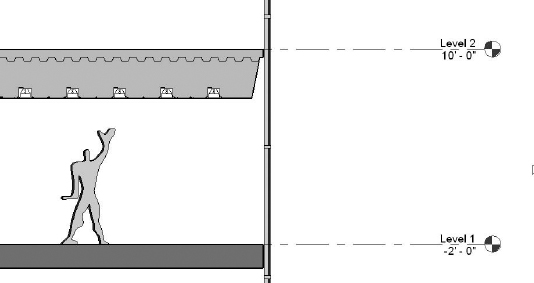
Activate the Section 1 view, and you should see that the floor sandwich assembly at Level 1 has been customized in a similar way to the floor at Level 2 (Figure 14.15). You can experiment with adding embellishing detail components as shown in the section.
FIGURE 14.15 The edge of the floor sandwich assembly for Level 1 has been customized.

Sketching for Floors, Ceilings, and Roofs
Because floors, ceilings, and roofs are sketch-based objects, the method you use when creating the boundary lines is critical to the behavior of the element to those around it. The recommended method is to use the Pick Walls option, as shown previously in Figure 14.5.
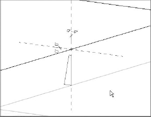
By selecting the walls to generate the sketch for the roof, you are creating an intelligent relationship between the walls and the roof. If the design of your building later changes and the wall position is modified, the roof will follow that change and adjust to the new wall position without any intervention from you (Figure 14.16).
FIGURE 14.16 Using the Pick method: (A) original roof; (B) the entrance wall position has changed, and the roof updates automatically; (C) the angle of the wall to the right of the entrance has changed, and the roof changes to a new shape.
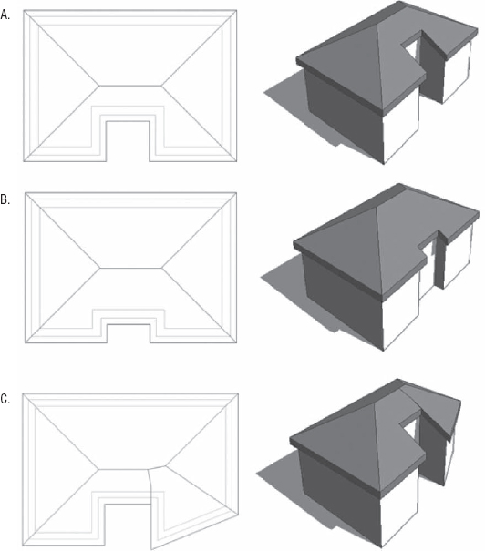
Also notice in Figure 14.16 that the illustrated roof was generated with overhangs beyond the exterior faces of the walls. You can specify an overhang or offset value for a floor, ceiling, or roof in the Options Bar before picking walls to define the sketch.
If your building design is using curtain walls, be careful with the location lines of these walls. The location line of a curtain wall is defined relative to the offsets specified in the mullion and panel families that comprise the curtain wall type. As discussed in Chapter 13, “Walls and Curtain Walls,” you have many options when defining the relative location line of your curtain wall types. Refer to the exercise in the “Structural Floor” section earlier in this chapter for an example of picking curtain walls with an offset based on a centered location line.