
Modeling Floor Finishes
You can apply floor finishes in a variety of ways. Most methods are based on the thickness of the finish material. For example, a thin finish such as carpet might be applied with the Split Face and Paint tools, whereas a thicker finish such as mortar-set stone tile might be a separate floor type.
Split Face for Thin Finishes
One of the easiest ways to divide a floor surface for thin finishes is using the Split Face and Paint tools. This method will require a floor to be modeled and an appropriate material defined with at least a surface pattern. Note that you can only schedule finishes applied with the Paint tool through Material Takeoff schedules. Let's explore this method with a quick exercise.
- Open the file c14-Design-Floor.rvt from the book's companion web page and activate the Level 1 floor plan. You will see an area of the floor that is bounded by a wall and two reference planes.
- Click the Modify tab in the ribbon, activate the Split Face tool from the upper-right corner of the Geometry panel, and pick the floor in the Level 1 floor plan.
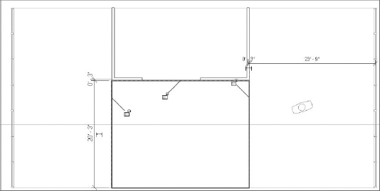
- Draw a rectangle in front of the three interior walls, as shown in Figure 14.17.
FIGURE 14.17 Sketch a rectangular boundary with the Split Face tool.
Note that you can constrain—or lock—the sketch lines to the interior walls, reference planes, and floor edge. You may do so in this exercise, but constraints should be used sparingly in larger projects to avoid slower model performance and updating calculation time.
Also note that you generated a complete rectangular sketch instead of only three bounding lines. You do not need to draw the boundary line at the edge of the floor; however, if you don't include that line and the floor shape is modified in the future, the split face may be deleted because it is no longer a closed-loop sketch.
- Click the Finish Edit Mode icon in the Mode panel.
- Return to the Modify tab in the ribbon and activate the Paint tool in the Geometry panel, just below the Split Face tool.
- At the right end of the ribbon, choose Carpet Tile from the Material drop-down list.
- In the Level 1 floor plan, click near the edge of the split face you created earlier to assign the material. The result should look like the sample shown in Figure 14.18.
FIGURE 14.18 Completed application of carpet tile material to a split face on a floor

Modeling Thick Finishes
Thicker finish materials such as tile, stone pavers, or terrazzo can be applied as unique floor types and modeled where required. For large areas of finish such as a public atrium or airport terminal, you can assign these materials within the layers of a floor assembly. When you need to add smaller areas of thick floor finishes, there are two scenarios you may encounter: with a depressed floor and without.
In areas such as bathrooms, a thick-set tile floor may require the structural slab to be depressed in order to accommodate the thickness of the finish material. In the example illustrated in Figure 14.19, the main floor object has been cut with an opening at the inside face of the walls. Another floor has been modeled with a negative offset value to accommodate the thickness of the tile material, and the tile has been placed as a unique floor element.
FIGURE 14.19 The thick tile finish and depressed slab are modeled as separate elements.

If you don't need a finish but just a slab depression, you can create it with an in-place void extrusion. Select the Home tab on the ribbon and click Component ![]() Model In-Place. Choose the Floors category and create a void extrusion where you need a slab depression. Remember to use the Cut Geometry tool to cut the void from the floor before finishing the family. As an alternative, you can create a floor-based generic family that contains a parametric void extrusion. You can download the file c14-Slab-Depression.rfa as an example of this type of family from the book's companion web page.
Model In-Place. Choose the Floors category and create a void extrusion where you need a slab depression. Remember to use the Cut Geometry tool to cut the void from the floor before finishing the family. As an alternative, you can create a floor-based generic family that contains a parametric void extrusion. You can download the file c14-Slab-Depression.rfa as an example of this type of family from the book's companion web page.
Finally, if the structural requirements allow a thick finish to be applied to a floor without dropping the structural slab, a finish floor element can be modeled directly in place within the structural slab. As shown in Figure 14.20, the tile floor has been graphically embedded in the structural floor using the Join Geometry tool. To do this, click the Modify tab on the ribbon and click Join Geometry. Be sure to pick the finish floor before the structural floor or you will get an error.
FIGURE 14.20 The thick tile finish floor has been joined with the structural floor.
