
Several pieces need to be in place before superelevation can be applied to the design. You will need a design criteria file appropriate for your region, design speeds applied to an alignment, and an assembly that is capable of superelevating.
There are a lot of abbreviations and terminology thrown around when it comes to superelevation, so let’s take a look at that first.
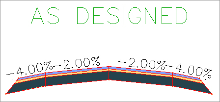
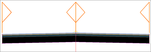
When an assembly is applied without superelevation, the geometry comes directly from the original design, as shown in Figure 11-1.
Figure 11-1: An example assembly without superelevation
As the assembly begins its entrance into a curve with superelevation applied to it, it will first start to lose its normal crown. Figure 11-2 shows the same assembly at the End Normal Crown (ENC) station.
Figure 11-2: At the End Normal Crown (ENC) station, the default lane slope starts to change.

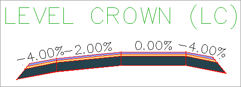
When the assembly has one side flattened out, as shown in Figure 11-3, this is called Level Crown (LC).
Figure 11-3: Level Crown entering a left-hand turn
When the assembly straightens out into a plane that matches the inside lane, this is called Reverse Crown (RC), as shown in Figure 11-4.
Figure 11-4: Reverse Crown (RC)

If accommodations have been made for shoulder slope rollover and breakover removal, the shoulder will shift as well. Figure 11-5a shows where the superelevated lane becomes steep enough to cause an outside rollover problem with the outside shoulder. The shoulder begins to adjust to increase the safety of the road. Figure 11-5b shows the change in the lower shoulder.
Figure 11-5: Begin Shoulder Rollover (BSR) (left) and Low Shoulder Match (LSM) (right)

Finally, the lane gets to its maximum slope at the Begin Full Super (BFS) station. As you can see in Figure 11-6, all the geometry adjustment has taken place.
Figure 11-6: Begin Full Super (BFS)

On the way out of the curve, you will see the geometry transitioning back to its original design. It will pass through End Full Super (EFS), Low Shoulder Match (LSM), Reverse Crown (RC), Level Crown (LC), Begin Normal Crown (BNC), and finally back to Begin Normal Shoulder (BNS).
Now that you are familiar with the terminology and abbreviations Civil 3D uses, let’s get started on some design.
Design Criteria Files
Having the correct design criteria file in place is the first step to applying superelevation to your corridor. These XML-based files contain instructions to the software on when to flag your design for geometry problems both horizontally and vertically. Design criteria files are the brains behind how your road behaves when superelevation is applied to the design.
Several design criteria files are supplied with Civil 3D upon installation. The out-of-the-box standards include AASHTO 2001 and AASHTO 2004 for both metric and US units. Several of the country kits include design criteria files for your locality if you are outside of the United States. If country or state kits do not exist for your situation, you can create your own, user-defined files.

To create your own design criteria, select any alignment and click the Design Criteria Editor icon from the context tab. It is easiest to modify an existing table in your desired units, rather than starting from an empty file. Be sure to click the Save As icon before making any changes.
User-Defined Criteria Files
If you create design criteria files for your region or design scenario, you will need to be able to share the file with anyone who will be working with your design.
Inside your organization, the best way to handle the design criteria file is to move it to a shared network location. If you are feeling squeamish that a less experienced person may accidentally modify the file, you can set the XML file to read-only.
The default location for design standards is :
C:ProgramDataAutodeskC3D 2012enuDataCorridor Design Standards
Once you re-path to the design criteria file for an alignment, the location will be saved with the alignment.
If you are collaborating with someone without direct access to your design criteria files, you will need to send that person the XML file with your DWG.
Inside the Design Criteria Editor (Figure 11-7), you will see three headings: Units, Alignments, and Profiles. The Units page tells Civil 3D what type values it will be using in the file. The Alignments page is used for checking design, creating superelevation, and widening outside curves. The Profiles page provides tabular data for minimum K value used to check vertical design.
Figure 11-7: Inside the Design Criteria Editor

This chapter will focus on the alignment-related tables in the file. Civil 3D will graphically flag alignments when the design speed specified in the alignment properties has a radius less than the value specified in the Minimum Radius Table. The Minimum Radius Tables from AASHTO use superelevation rates in the table names, but this does not lock you into that rate for applying superelevation to the corridor. In other words, just because you use a more conservative value in your radius check, that doesn’t mean you can’t superelevate at a steeper rate. The tables are independent of one another.
Also in the Alignments page you will find the superelevation attainment equations. These equations determine the distance between superelevation critical stations. Familiarize yourself with the terminology and locations represented by these stations, as shown in Figure 11-8.
Figure 11-8: Superelevation critical stations and regions calculated by Civil 3D
In the following exercise, you will modify an example design criteria file and save it:
1. Open the Highway 10 Criteria.dwg file, which you can download from this book’s web page at www.sybex.com/go/masteringcivil3d2012.
2. Select the Highway 10 alignment that already exists in the drawing. From the Modify panel on the context tab, select Design Criteria Editor.
3. Click the Open button at the top of the dialog box. Browse to the MasteringExample.xml file.
4. Expand the Alignments category. Expand the Superelevation Tables area. There is only one superelevation table in this example for 4% maximum slope. Right-click on Superelevation Tables and select New Superelevation Table.
5. Double-click the new table and rename it Example 6% Super.
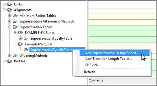
6. Right-click on Example 6% Super and select New SuperelevationTypeByTable. Expand the new section. Right-click SuperelevationTypeByTable and select New Superelevation Design Speed, as shown in Figure 11-9.
Figure 11-9: Adding a design speed to the design criteria file
7. Civil 3D will place a new design speed with a default of 10mph in the listing. Double-click the Design Speed 10 and change the design speed to 30.
8. Highlight your example design speed. The right side of the dialog box will have an empty table containing columns for Radius and Superelevation Rate. Click the first field in the Radius column to start entering data. Add several radius and superelevation values, as shown in Figure 11-10.
Figure 11-10: Adding example data using the Design Criteria Editor
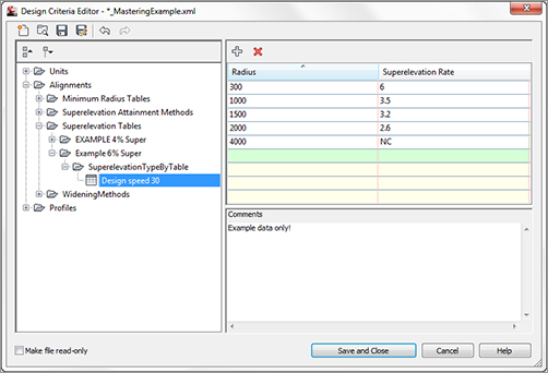
9. Add a note in the Comment field that reads Example Data Only.
10. Click the Save And Close button at the bottom of the editor. Click Save Changes and exit when prompted.
Ready Your Alignment
Superelevation stations are connected to alignment curves. The design speed from the alignment properties is needed at each curve to specify which superelevation rate tables to use from the design criteria. The design speed has an effect on the distance between superelevation critical stations and the cross-slope used when the road is at full-super.
It is a good idea to get your alignment geometry and design speed locations finalized before attaching superelevation. If a change is made to your alignment, the superelevation stationing will be marked as out of date.
Super Assemblies
As a general rule, if the lane subassembly has the word “super” somewhere in its name, it will respond to superelevation. If you want to verify that the lane you are choosing will behave the way you want it to in a superelevation situation, you can right-click it from the tool palette and access the subassembly help.
As long as you stay away from the Basic tab, all of the shoulder and curb subassemblies have parameters you can set to dictate how the assembly is to behave when an adjacent lane superelevates.
Most subassemblies that are capable of superelevating are intended for use where the pivot point for the cross section is at the center crown of the road. When the pivot point is at the center of the road, the baseline profile dictates the final elevation of the crown of the road. Figure 11-4 shows an example of a two-lane highway (a) and a four-lane divided highway (b) that are designed to be used with the superelevation tools. The examples in Figure 11-11 show assemblies that will superelevate using the center crown of the road as a pivot point.
Figure 11-11: Two-lane road ready for super (a); four-lane road used in super (b)

Axis of Rotation Support
The newest addition to the subassembly family is the LaneSuperelevationAOR. This axis of rotation (AOR) subassembly can be used when the centerline of the road is not the pivot point for superelevation. The “flag” symbols (as shown in Figure 11-12) indicate potential pivot points on the assembly.
Figure 11-12: AOR subassemblies used on an undivided, crowned roadway
The flag symbols on LaneSuperelevationAOR indicate where the lane can be pinned down and used as a pivot point. When the axis of rotation is not the centerline of the road, the lane geometry is used to determine the change in elevation that will occur as a result.
Axis of Rotation (AOR)
The following is a list of the limitations and other factors to be aware of if you decide to take these new assemblies for a spin:
- Don’t use an offset assembly with an axis of rotation superelevation assembly. Doing so can throw off the superelevation calculation.
- When working with curbs, medians, and shoulders, keep an eye out for the parameter SE AOR Unsupported. If this parameter is set to 1, it means that the subassembly will not adjust for superelevations other than at the center. None of the curb and gutter subassemblies will adjust for breakover or rollover, but most of the shoulder assemblies do. This is a “hard-coded” parameter that cannot be changed by the end user.
The Tipping Point
In some design situations that use superelevation, the crown of the road is not the ideal pivot point. In the following example, you will create a four-lane divided highway that pivots inside the curve rather than at the crowns during superelevation.
1. Open the file AOR Assembly.dwg.
2. Zoom into the assembly that was started for you in this drawing. Note that a generic link has been placed on each side as a spacer for the subassemblies that you will be adding in the next steps.
3. Open your subassembly tool palette and find the Lanes tab. Select the LaneSuperelevationAOR subassembly.
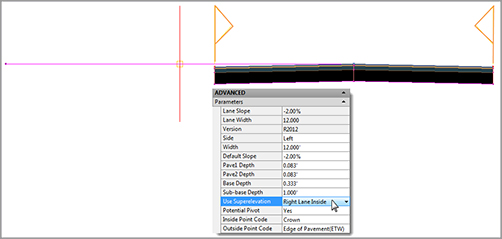
4. In the Advanced Parameters of the properties, set Side to Right and Use Superelevation to Right Lane Outside.
5. Place the subassembly on the right side, using the generic link marker as its “hanger.”

6. Change the Advanced Parameters so that Side is set to Left and Use Superelevation is set to Right Lane Inside. Place this subassembly in the drawing to form the lane as shown here.
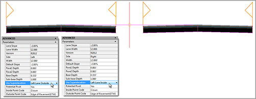
7. Repeat the process for the left side of the assembly. Use the following graphic to help set the correct sides and superelevation parameters. Note that the inside lane must be set to Left Lane Inside and the outside lane must be set to Left Lane Outside.
8. Select the MarkPoint subassembly from the Generic tab. Name the Marker MEDIAN and place it on the inside left edge of pavement.
9. On the Medians tab, select MedianDepressed. Be sure the Marked Point Name is set to MEDIAN.

10. As the final step in building this assembly, select both of the original generic link spacers and set the Omit Link property to Yes. If time permits, add the ShoulderExtendAll subassembly to the outermost edges.

11. Select the alignment that runs through the project. On the context tab, click Superelevation Calculate/Edit Superelevation. Click the Calculate Superelevation Now option when notified that no data exists.
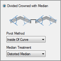
12. Set the Roadway Type to Divided Crown With Median. Set the Pivot method to Inside Of Curve. Set the Median treatment to Distorted Median. Click Next.
13. On the Lanes page, set the normal lane width to 12′ and the normal lane slope to -2.00% for a Symmetric Roadway. Click Next.
14. On the Shoulder Control page, leave the settings at their defaults and click Next.
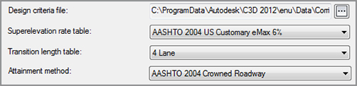
15. On the Attainment page, set the active criteria file to Autodesk Civil 3D Imperial (2004) Roadway Design Standards.xml. Set the Superelevation rate table to AASHTO 2004 Customary eMax 6%, using the 4 Lane Transition Length table. Toggle on Automatically Resolve Overlap. Click Finish.
16. In Prospector, select the Corridor, right-click, and select Properties. Right-click on BL-Route 66 and select Add Region. Select the Route 66 Main assembly and click OK. Click OK to let the corridor build.
17. Select the corridor in plan and enter the Section Editor to examine your corridor. You should observe that superelevation is occurring based on our specified pivot point of inside the curves.
