
Best Practices for Parcel Creation
Now that you have an understanding of how objects in a site interact and you’ve had some practice creating and editing parcels in a variety of ways, we’ll take a deeper look at how parcels must be constructed to achieve topology stability, predictable labeling, and desired parcel interaction.
Forming Parcels from Segments
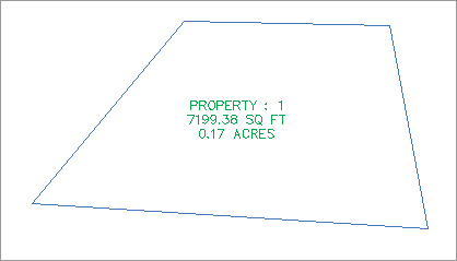
In the earlier sections of this chapter, you saw that parcels are created only when parcel segments form a closed area (see Figure 5-41).
Figure 5-41: A parcel is created when parcel segments form a closed area.
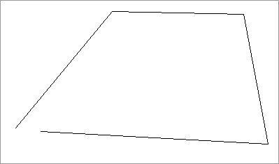
Parcels must always close. Whether you draw AutoCAD lines and use the Create Parcel From Objects menu command or use the parcel segment creation tools, a parcel won’t form until there is an enclosed polygon. Figure 5-42 shows four parcel segments that don’t close; therefore, no parcel has been formed.
Figure 5-42: No parcel will be formed if parcel segments don’t completely enclose an area.
There are times in surveying and engineering when parcels of land don’t necessarily close when created from legal descriptions. In this case, you must work with your surveyor to perform an adjustment or find some other solution to create a closed polygon.
You also saw that even though parcels can’t be erased, if you erase the appropriate parcel segments, the area contained within a parcel is assimilated into neighboring parcels.
Parcels Reacting to Site Objects
Parcels require only one parcel segment to divide them from their neighbor (see Figure 5-43). This behavior eliminates the need for duplicate segments between parcels, and duplicate segments must be avoided.
Figure 5-43: Two parcels, with one parcel segment between them
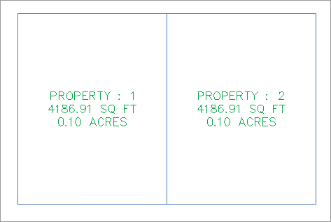
As you saw in the section on site interaction, parcels understand their relationships to one another. When you create a single parcel segment between two subdivision lots, you have the ability to move one line and affect two parcels. Figure 5-44 shows the moved parcels from Figure 5-43 once the parcel segment between them has been shifted to the left. Note that both areas change in response.
Figure 5-44: Moving one parcel segment affects the area of two parcels.

A mistake that many people new to Civil 3D make is to create parcels from closed polylines, which results in a duplicate segment between parcels. Figure 5-45 shows two parcels created from two closed polylines. These two parcels may appear identical to the two seen in the previous example, because they were both created from a closed polyline rectangle; however, the segment between them is actually two segments.
Figure 5-45: Adjacent parcels created from closed polylines create overlapping or duplicate segments.
The duplicate segment becomes apparent when you attempt to grip-edit the parcel segments. Moving one vertex from the common lot line, as seen in Figure 5-46, reveals the second segment. Also note that a sliver parcel is formed. Duplicate site geometry objects and sliver parcels make it difficult for Civil 3D to solve the site topology and can cause drawing stability problems and unexpected parcel behavior. You must avoid this situation at all costs. Creating a subdivision plat of parcels this way almost guarantees that your labeling won’t perform properly and could potentially lead to data loss and drawing corruption.
Figure 5-46: Duplicate segments become apparent when they’re grip-edited and a sliver parcel is formed.

Migrating Parcels from Land Desktop
The Land Desktop Parcel Manager essentially created Land Desktop parcels from closed polylines. If you migrate Land Desktop parcels into Civil 3D, your resulting Civil 3D parcels will behave poorly and will almost universally result in drawing corruption.
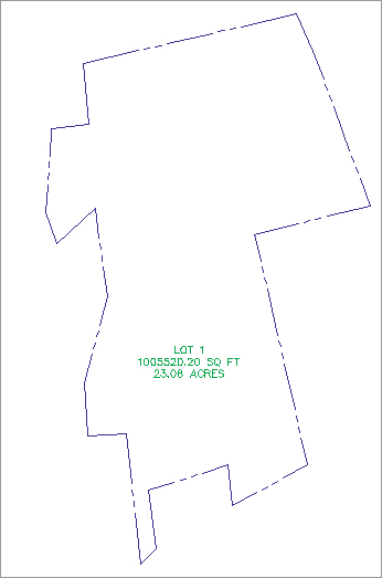
Parcels form to fill the space contained by the original outer boundary. You should always begin a parcel-division project with an outer boundary of some sort (see Figure 5-47).
Figure 5-47: An outer boundary parcel
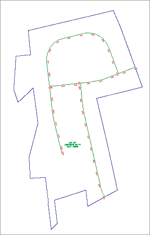
You can then add road centerline alignments to the site, which divides the outer boundary as shown in Figure 5-48.
Figure 5-48: Alignments added to the same site as the boundary parcel divide the boundary parcel.
It’s important to note that the boundary parcel no longer exists intact. As you subdivide this site, parcel 1 is continually reallocated with every division. As road ROW and subdivision lots are formed from parcel segments, more parcels are created. Every bit of space that was contained in the original outer boundary is accounted for in the mesh of newly formed parcels (see Figure 5-49).
Figure 5-49: The total area of parcels contained within the original boundary sums to equal the original boundary area.

From now on, you’ll consider ROW, wetlands, parkland, and open space areas as parcels, even if you didn’t before. You can make custom label styles to annotate these parcels however you like, including a “no show” or none label.
If I Can’t Use Closed Polylines, How Do I Create My Parcels?
How do you create your parcels if parcels must always close, but you aren’t supposed to use closed polylines to create them?
In the earlier exercises in this chapter, you learned several techniques for creating parcels. These techniques included using AutoCAD objects and a variety of parcel layout tools. Here’s a summary of some of the best practices for creating parcels:
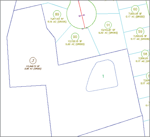
- Create closed polylines for boundaries and islands, and then use the Create Parcel From Objects menu command. Closed polylines are suitable foundation geometry in cases where they won’t be subject to possible duplicate segments. The following graphic shows a boundary parcel and a designated open space parcel that were both created from closed polylines. Other examples of island parcels include isolated wetlands, ponds, or similar features that don’t share a common segment with the boundary parcel.
- Create trimmed/extended polylines for internal features, and then use the Create Parcel From Objects menu command. For internal features such as easements, buffers, open space, or wetlands that share a segment with the outer boundary, draw a polyline that intersects the outer boundary, but be careful not to trace over any segments of the outer boundary. Use the Create Parcel From Objects menu command to convert the polyline into a parcel segment. The following graphic shows an easement.
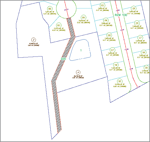
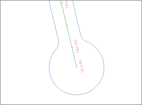
- Use the Create ROW tool or create trimmed/extended polylines, and then use the Create Parcel From Objects menu command for ROW segments. In a previous exercise, you used the Create ROW tool. You also learned that even though this tool can be useful, it can’t create cul-de-sacs or changes in ROW width. In cases where you need a more intricate ROW parcel, use the AutoCAD Offset tool to offset your alignment. The resulting offsets are polylines. Use circles, arcs, fillet, trim, extend, and other tools to create a joined polyline to use as foundation geometry for your ROW parcel. Use the Create Parcel From Objects menu command to convert this linework into parcel segments for a cul-de-sac, as shown here.
- Create trimmed or extended polylines for rear lot lines, and then use the Create Parcel From Objects menu command. The precise sizing tools tend to work best when given a rear lot line as a target endpoint. Create this rear target by offsetting your ROW parcel to your desired lot depth. The resulting offset is a polyline. Use Trim, Extend, and other tools to create a joined polyline to use as foundation geometry for your rear lot parcel segment. Surveyors often prefer to lay out straight-line segments rather than curves, so for the final rear lot line cleanup, create AutoCAD lines across the back of each lot and then use Create Parcel From Objects to turn those lines into parcel segments, as shown here.

This final cleanup is best saved for the very end of the project. Parcel iterations and refinement work much better with a continuous rear lot line.
Constructing Parcel Segments with the Appropriate Vertices
Parcel segments should have natural vertices only where necessary and split-created vertices at all other intersections. A natural vertex, or point of intersection (PI), can be identified by picking a line, polyline, or parcel segment and noting the location of the grips (see Figure 5-50).
Figure 5-50: Natural vertices on a parcel segment
A split-created vertex occurs when two parcel segments touch or cross each other. Note that in Figure 5-51, the parcel segment doesn’t show a grip even where each individual lot line touches the ROW parcel.
Figure 5-51: Split-created vertices on a parcel segment

It’s desirable to have as few natural vertices as possible. In the example shown previously in Figure 5-50, the ROW frontage line can be expressed as a single bearing and length from the end of the arc through the beginning of the next arc, as opposed to having several smaller line segments.
If the foundation geometry was drawn with a natural vertex at each lot line intersection, then the resulting parcel segment won’t label properly and may cause complications with editing and other functions. This subject will be discussed in more detail later in the section “Labeling Spanning Segments,” later in this chapter.
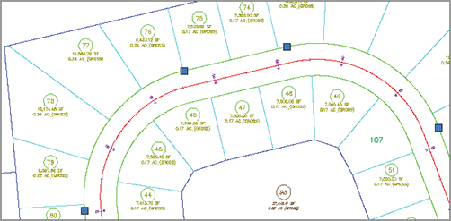
Parcel segments must not overlap. Overlapping segments create redundant vertices, sliver parcels, and other problems that complicate editing parcel segments and labeling as shown in Figure 5-52. Figure 5-53 shows a segment created to form parcel 3 that overlaps the rear parcel segment for the entire block. This segment should be edited to remove the redundant parcel segment across the rear of Parcel 90 to ensure good parcel topology.
Figure 5-52: Avoid creating overlapping parcel segments.

Parcel segments must not overhang. Spanning labels are designed to overlook the location of intersection formed (or T-shaped) split-created vertices. However, these labels won’t span a crossing formed (X- or + [plus]-shaped) split-created vertex. Even a very small parcel segment overhang will prevent a spanning label from working and may even affect the area computation for adjacent parcels. The overhanging segment in Figure 5-53 would prevent a label from returning the full spanning length of the ROW segment it crosses.
Figure 5-53: Overhanging segment
