
A question many people ask when working with corridors is, “At what point do I need another region?” The answer is simple: If you need a different assembly, you need a different region.
In the following example, you will step through adding an additional region to an existing baseline:
1. Open the drawing Multi-Region Corridor.dwg.
2. Select the corridor that exists in the drawing and select Corridor Properties from the contextual Ribbon tab.
3. On the Parameters tab, notice there is a baseline containing a single region. Right-click on the region and select Split Region, as shown in Figure 10-11.
Figure 10-11: Right-click to access Region Creation tools.

4. At the command line, enter 4000↵ to create a split at 40+00. Create a second split at 55+00 by entering 5500↵. Press ↵ again to return to the Corridor Parameters dialog. (If you see a warning dialog referring to 0+00 being outside of the station limits, click OK and continue.)
5. You should have three regions at this step, as shown in Figure 10-12. Change the assembly for the middle region to use the 12′ Lane Road w Guardrail assembly.
Figure 10-12: New regions with different assemblies applied

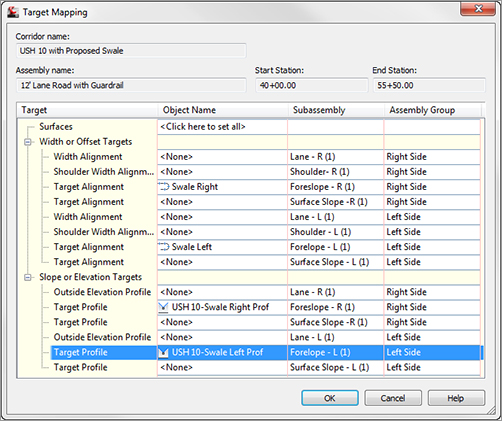
6. Scroll over and click the Target ellipsis button. Notice that the Targets have reset to <none> for this region. Set the Targets as shown in Figure 10-13. Click OK when Target Mapping is complete. Then click OK to build the corridor.
Figure 10-13: Targets for the middle region
7. You should now see additional feature lines in the plan view representing the top of the guardrail. If you choose to examine the corridor in the Object Viewer, it will resemble Figure 10-14.
Figure 10-14: The completed corridor with guardrails
