
A corridor provides the raw material for surface creation. Just as you would use points and breaklines to make a surface, a corridor surface uses corridor points as point data and uses feature lines and links like breaklines.
The Corridor Surface
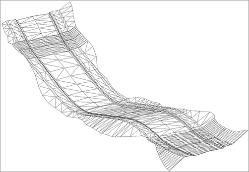
Civil 3D does not automatically build a corridor surface when you build a corridor. From examining subassemblies, assemblies, and the simple corridors you built in the previous exercises, you have probably noticed that there are many “layers” of points, links, and feature lines. Some represent the very top of the finished ground of your road design, some represent subsurface gravel or concrete thicknesses, and some represent subgrade, among other possibilities. You can choose to build a surface from any one of these layers or from all of them. Figure 9-34 shows an example of a TIN surface built from the links that are all coded Top, which would represent final finished ground.
Figure 9-34: A surface built from Top code links
When you first create a surface from a corridor, the surface is dependent on the corridor object. This means that if you change something that affects your corridor and then rebuild the corridor, the surface will also update.
A corridor surface shows up as a true surface under the Surfaces branch in Prospector. After you create the initial corridor surface, you can create a static export of the surface by changing to the Home tab and choosing Surfaces Create Surface From Corridor on the Create Ground Data panel. A detached surface will not react to corridor changes and can be used to archive a version of your surface.
Creation Fundamentals
You create corridor surfaces on the Surfaces tab in the Corridor Properties palette using the following two steps (which are examined in detail later in this section):
Click Create A Corridor Surface to add a surface entry. Then choose data to add, and click the + sign.
You can choose to create your corridor surface on the basis of links, feature lines, or a combination of both.
Creating a Surface from Link Data
Most of the time, you will build your corridor surface from links. As discussed earlier, each link is coded with a name such as Top, Pave, Datum, and so on. Choosing to build a surface from Top links will create a surface that triangulates between the points at the link vertices that represent the final finished grade.
The most commonly built link-based surfaces are Top and Datum; however, you can build a surface from any link code in your corridor. Figure 9-35 shows a schematic of how links are used to form the most common surfaces.
Figure 9-35: Schematic of Top links connecting to form a surface (a) and schematic of Datum links connecting to form a surface (b)

Overhang Correction for Whacked-out Datum Surfaces
A common situation with assemblies is a material that juts out past another material, such as curb sub-base. Triangulated surfaces cannot contain caves or perfectly vertical faces, so Civil 3D needs to go around the material in a logical manner. What Civil 3D sees as logical and what you actually want from the surface may not agree, as shown here:

If you have a datum surface doing an unexpected zig-zag, change the Overhang Correction setting to Bottom Links. This setting is in the Corridor Properties – Surfaces tab. After your corridor rebuilds, the result will resemble Figure 9-35b.
When building a surface from links, you have the option of checking a box in the Add As Breakline column. Checking this box will add the actual link lines themselves as additional breaklines to the surface. In most cases, especially in intersection design, checking this box forces better triangulation.
Creating a Surface from Feature Lines
There might be cases where you would like to build a simple surface from your corridor—for example, by using just the crown and edge-of-travel way. If you build a surface from feature lines only or a combination of links and feature lines, you have more control over what Civil 3D uses as breaklines for the surface.
If you added all the topmost corridor feature lines to your surface entry and built a surface, you would get a very similar result as if you had added the Top link codes.
Creating a Surface from Both Link Data and Feature Lines
A link-based surface can be improved by the addition of feature lines. A link-based surface does not automatically include the corridor feature lines, but instead uses the link vertex points to create triangulation. Therefore, the addition of feature lines ensures that triangulation occurs where desired. This is especially important for intersection design, curves, and other corridor surfaces where triangulation around tight corners is critical. Figure 9-36 shows the Surfaces tab of the Corridor Properties dialog where a Top link surface will be improved by the addition of Back_Curb, ETW, and Top_Curb feature lines.
Figure 9-36: The Surfaces tab indicates that the surface will be built from Top links as well as from several feature lines.

If you are having trouble with triangulation or contours not behaving as expected, experiment with adding a few feature lines to your corridor surface definition.
Other Surface Tasks
You can do several other tasks on the Surfaces tab. You can set a Surface Style, assign a meaningful name, and provide a description for your surface. Alternatively, you can do all those things once the surface appears in the drawing and through Prospector.
Adding a Surface Boundary
Surface boundaries are critical to any surface, but especially so for corridor surfaces. Tools that automatically and interactively add surface boundaries, using the corridor intelligence, are available. Figure 9-37 shows a corridor surface before the addition of a boundary.
Figure 9-37: A corridor surface before the addition of a boundary

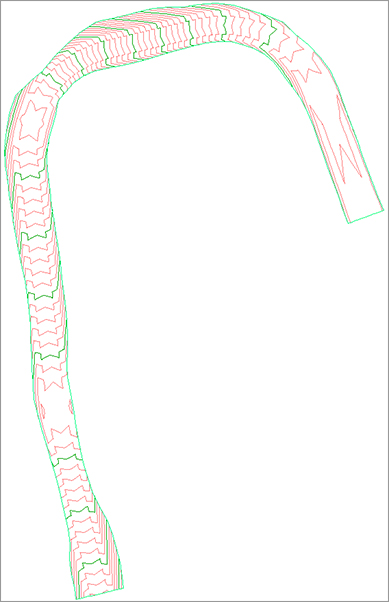
You can create corridor surface boundaries using the Boundaries tab of the Corridor Properties dialog. Figure 9-38 shows a corridor surface after the application of an automatic boundary. Notice how the extraneous contours have been eliminated along the line of intersection between the existing ground and the proposed ground (the daylight line), thereby creating a much more accurate surface.
Figure 9-38: A corridor surface after the addition of an automatic daylight boundary
Boundary Types
There are several tools to assist in corridor surface boundary creation. They can be automatic, semiautomatic, or manual in nature depending on the complexity of the corridor.
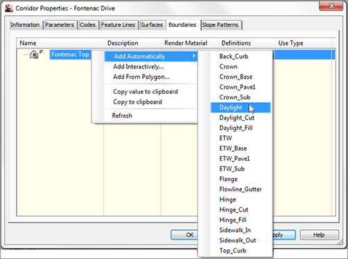
You access these options on the Boundaries tab of the Corridor Properties dialog by right-clicking the name of your surface entry, as shown in Figure 9-39.
Figure 9-39: Corridor Surface Boundary options for a corridor containing a single baseline
The following corridor boundary methods are listed in order of desirability. Corridor Extents As Outer Boundary is the most user-friendly, whereas Add From Polygon is fast but needs constant updating as it is not dynamically linked to the corridor.
Corridor Extents As Outer Boundary This option is available only when you have a corridor with multiple baselines. With this selection, Civil 3D will shrink-wrap the corridor, taking into account intersections and various daylight options on different alignments. Corridor Extents As Outer Boundary will probably be your most-used boundary option.
Add Automatically The Add Automatically boundary tool allows you to pick a feature line code to use as your corridor boundary. This tool is available only for single-baseline corridors. Because this tool is the most automatic and easiest to apply, you will use it almost every time you build a single-baseline corridor.
Add Interactively The Add Interactively boundary tool allows you to work your way around a multibaseline corridor and choose which corridor feature lines you would like to use as part of the boundary definition.
This is the better option than Add From Polygon if Add Automatically and Corridor Extents are not available. It takes a bit of patience to trace the corridor, but the result is a dynamically linked boundary that changes if the corridor changes.
Add From Polygon The Add From Polygon tool allows you to choose a closed polyline or polygon in your drawing that you would like to add as a boundary for your corridor surface. This method is quick, but the resulting boundary is not dynamic to your design.
The next exercise leads you through creating a corridor surface with an automatic boundary:
1. Open the Corridor Surface.dwg file. Note that there is a completed corridor in this drawing.
2. Pick the Frontenac Drive corridor and select Corridor Properties from the Modify panel. The Corridor Properties dialog opens.
3. Switch to the Surfaces tab.
4. Click the Create A Corridor Surface button on the far left side of the dialog. You should now have a surface entry in the bottom half of the dialog.
5. Click the surface entry under the Name column and change the default name of your surface to Frontenac-Top Surface.
6. Confirm that Links has been selected from the drop-down menu in the Data Type selection box and that Top has been selected from the drop-down menu in the Specify Code selection box. Click the + button to add Top Links to the Surface Definition.
7. Click OK to leave this dialog, and examine your surface. The road surface should look fine; however, because you have not yet added a boundary to this surface, undesirable triangulation is occurring outside your corridor area.
8. Expand the Surfaces branch in Prospector. Note that you now have a corridor surface listed.
9. Pick the corridor and select Corridor Properties from the Modify panel. The Corridor Properties dialog opens. (If the Corridor Properties button is not available on the Modify panel, you may have accidentally chosen the corridor surface.)
10. In the Corridor Properties dialog, switch to the Boundaries tab.
11. Right-click Frontenac – Top Surface in the listing. Hover over the Add Automatically flyout, and select Daylight as the feature line that will define the outer boundary of the surface.
12. Confirm that the Use Type column says Outside Boundary to ensure that the boundary definition will be used to define the desired extreme outer limits of the surface.
13. Click OK to dismiss the dialog. Examine your surface, and note that the triangulation terminates at the Daylight point all along the corridor model.
14. Experiment with making changes to your finished grade profile, assembly, or alignment geometry and rebuilding both your corridor and finished ground surface.
Rebuild: Leave It On or Off?
Upon rebuilding your corridor, your surface will need to be updated. Typically, the best practice is to leave Rebuild – Automatic off for corridors and keep Rebuild – Automatic on for surfaces. This practice is usually OK for your corridor-dependent surfaces. The surface will only want to rebuild when the corridor is rebuilt. For very large corridors, this may become a bit of a memory lag, so try it both ways to see what you like best.
Common Surface Creation Problems
Some common problems encountered when creating surfaces are as follows:
Problem Your corridor surface does not appear or seems to be empty.
Typical Cause You might have created the surface entry but no data.
Fix Open the Corridor Properties dialog and switch to the Surfaces tab. Select an entry from the drop-down menus in the Data Type and Specify Code selection boxes, and click the + sign. Make sure your dialog shows both a surface entry and a data type, as shown in Figure 9-40.
Figure 9-40: A surface cannot be created without both a surface entry and a data type.
Problem Your corridor surface does not seem to respect its boundary after a change to the assembly or surface-building data type (in other words, you switched from link data to feature lines).
Typical Cause Automatic and interactive boundary definitions are dependent on the codes used in your corridor. If you remove or change the codes used in your corridor, the boundary needs to be redefined.
Fix Open the Corridor Properties dialog and switch to the Boundaries tab. Erase any boundary definitions that are no longer valid (if any). Redefine your boundaries.
Problem Your corridor surface seems to have gaps at PCs and PTs near curb returns.
Typical Cause You may have encountered an error in rounding at these locations, and you may have inadvertently created gaps in your corridor. This is commonly the result of building a corridor using two-dimensional linework as a guide, but some segments of that linework do not touch.
Fix Be sure your corridor region definitions produce no gaps. You might consider using the PEDIT command to join lines and curves representing corridor elements that will need to be modeled later. You might also consider setting a COGO point at these locations (PCs, PTs, and so on) and using the Node object snap instead of the Endpoint object snap to select the same location each time you are required to do so.