
Working with vertical data is an integral part of building the Civil 3D model. Once profile information has been created in any number of ways, displaying it to make sense is another task. It can’t be stated enough that profiles and profile views are not the same thing in Civil 3D. The profile view is the method that Civil 3D uses to display profile data. A single profile can be shown in an infinite number of views, with different grids, exaggeration factors, labels, or linetypes. In this part of the chapter, you’ll look at the various methods available for creating profile views.
Creating Profile Views During Sampling
The easiest way to create a profile view is to draw it as an extended part of the surface sampling procedure. In this brief exercise, you’ll sample a surface and then create the view in one series of steps:
1. Open the ProfileViews.dwg file. (Remember, all data files can be downloaded from this book’s web page.)
2. Change to the Home tab and select Profile Create Surface Profile from the Create Design panel to display the Create Profile From Surface dialog.
3. In the Alignment text box, select Syrah Way. In the Select Surface list box, select the EG surface. Click the Add button.
4. Click the Draw In Profile View button to move into the Create Profile View wizard, shown in Figure 7-45.
Figure 7-45: The Create Profile View wizard
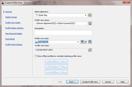
Profile views are created with the help of a wizard. The wizard offers the advantage of stepping through all the options involved in creating a view or simply accepting the command settings and creating the profile view quickly and simply.
5. Verify that Syrah Way is selected in the Alignment drop-down list and Profile View is selected in the Profile View Style, and click Next.
6. Verify that the Station Range area has the Automatic option selected and click Next.
7. Verify that the Profile View Height field has the Automatic option selected and click Next.
8. Click the Create Profile View button in the Profile Display Options window.
9. Pick a point on screen somewhere to the right of the site and surface to draw the profile view, as shown in Figure 7-46.
Figure 7-46: The completed profile view for Syrah Way
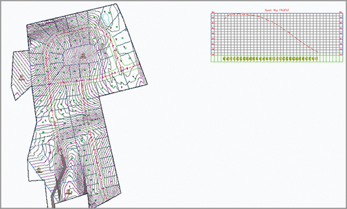
By combining the profile sampling step with the creation of the profile view, you have avoided one more trip to the menus. This is the most common method of creating a profile view, but we’ll look at a manual creation in the next section.
Creating Profile Views Manually
Once an alignment has profile information associated with it, any number of profile views might be needed to display the proper information in the right format. To create a second, third, or tenth profile view once the sampling is done, you must use a manual creation method. In this exercise, you’ll create a profile view manually for an alignment that already has a surface-sampled profile associated with it:
1. Open the ProfileViews.dwg file if you have not already done so.
2. Change to the Home tab and select Profile View Create Profile View from the Profile & Section Views panel.
3. In the Select Alignment text box, select Cabernet Court from the drop-down list. The profile was already sampled from the surface.
4. In the Profile View Style drop-down list, select the Full Grid style.
5. Click the Create Profile View button and pick a point on screen to draw the profile view, as shown in Figure 7-47.
Figure 7-47: The completed profile view of Cabernet Court

Using these two creation methods, you’ve made simple views, but you look at a longer alignment in the next exercise, and some more of the options available in the Create Profile View wizard.
Splitting Views
Dividing up the data shown in a profile view can be time consuming. Civil 3D’s Profile View wizard is used for simple profile view creation, but the wizard can also be used to create manually limited profile views, staggered (or stepped) profile views, multiple profile views with gaps between the views, and stacked profiles (aka three-line profiles). You’ll look at these variations on profile view creation in this section.
Creating Manually Limited Profile Views
Continuous profile views like you made in the first two exercises work well for design purposes, but they are often unusable for plotting or exhibiting purposes. In this exercise, you’ll sample a surface, and then use the wizard to create a manually limited profile view. This variation will allow you to control how long and how high each profile view will be, thereby making the views easier to plot or use for other purposes.
1. Open the ProfileViewsSplit.dwg file.
2. Change to the Home tab and select Profile Create Surface Profile from the Create Design panel to display the Create Profile From Surface dialog.
3. In the Alignment text box, select Frontenac Drive; in the Select Surface list box, select the EG surface and click the Add button.
4. Click the Draw In Profile View button to enter the wizard.
5. In the Profile View Style drop-down list, select the Full Grid style and click Next.
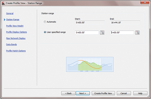
6. In the Station Range area, select the User Specified Range radio button. Enter 0 for the Start station and 8+00 for the End station, as shown in Figure 7-48. Notice the preview picture shows a clipped portion of the total profile. Click Next.
Figure 7-48: The start and end stations for the user-specified profile view
7. In the Profile View Height area, select the User Specified radio button. Set the Minimum height to 781 and the Maximum height to 820.
8. Click the Create Profile View button and pick a point on screen to draw the profile view. Your screen should look similar to Figure 7-49.
Figure 7-49: Applying user-specified station and height values to a profile view

Creating Staggered Profile Views
When large variations occur in profile height, the graph must often be split just to keep from wasting much of the page with empty grid lines. In this exercise, you use the wizard to create a staggered, or stepped, view:
1. Open the ProfileViewsStaggered.dwg file.
2. Change to the Home tab and select Profile Create Surface Profile from the Create Design panel to display the Create Profile From Surface dialog.
3. In the Alignment text box, select Frontenac Drive; in the Select Surface list box, select the EG surface and click the Add button.
4. Click the Draw In Profile View button to enter the wizard. Click Next to move to the Station Range options.
5. Make sure that Station Range is set to Automatic to allow the view to show the full length. Click Next.
6. In the Profile View Height field, select the User Specified option and set the values to 785.00′ and 825.00′ as shown in Figure 7-50.
Figure 7-50: Split Profile View settings
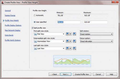
7. Check the Split Profile View options and set the view styles, as shown in Figure 7-50.
8. Click the Create Profile View button and pick a point on screen to draw the staggered display, as shown in Figure 7-51.
Figure 7-51: A staggered (stepped) profile view created via the wizard
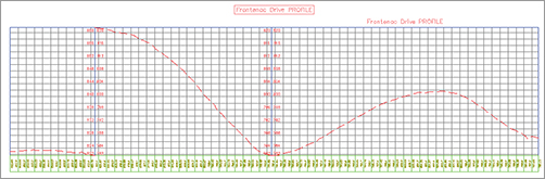
The profile view is split into views according to the settings that were selected in the Create Profile View wizard in step 7. The first section shows the profile from 0 to the station where the elevation change of the profile exceeds the limit for height. The next section displays the same and so forth for the rest of the profile. Each of these sections is part of the same profile view and can be adjusted via the Profile View Properties dialog.
Creating Gapped Profile Views
Profile views must often be limited in length and height to fit a given sheet size. Gapped views are a way to show the entire length and height of the profile, by breaking the profile into different sections with “gaps” or spaces between each view.
When you are using the Plan and Production Tools (covered in Chapter 16, “Plan and Production”), the gapped profile views are automatically created.
In this exercise, you use a variation of the Create Profile View wizard to create gapped views automatically:
1. Open the ProfileViewsStaggered.dwg file if you haven’t already. If you did the previous exercise, skip steps 2 and 3.
2. Change to the Home tab and select Profile Create Surface Profile from the Create Design panel to display the Create Profile From Surface dialog.
3. In the Alignment text box, select Frontenac Drive; in the Select Surface list box, select the EG surface and click the Add button. Click OK to exit the dialog.
4. Change to the Home tab and select Profile View Create Multiple Profile Views to display the Create Multiple Profile Views wizard (see Figure 7-52).
Figure 7-52: The Create Multiple Profile Views wizard
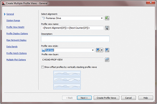
5. In the Select Alignment drop-down list, select Frontenac Drive, and in the Profile View Style drop-down list, select the Full Grid option, as shown in Figure 7-52. Click Next.
6. On the Station Range page, make sure the Automatic option is selected. This page is also where you set the length of each view. Click Next.
7. On the Profile View Height page, make sure the Automatic option is selected. Note that you could use the Split Profile View options from the previous exercise here as well. Click Next.
8. On the Profile Display Options page, scroll across until you get to Labels. Change the style to _No Labels.
9. Click the Multiple Plot Options text on the left side of the page to jump to that step in the wizard. This step controls whether the gapped profile views will be arranged in a column, row, or a grid. The Frontenac Drive alignment is fairly short, so the gapped views will be aligned in a row. However, it could be prudent with longer alignments to stack the profile views in a column or a compact grid, thereby saving screen space.
10. Click the Create Profile Views button and pick a point on screen to create a view similar to Figure 7-53.
Figure 7-53: The staggered and gapped profile views of the Frontenac alignment
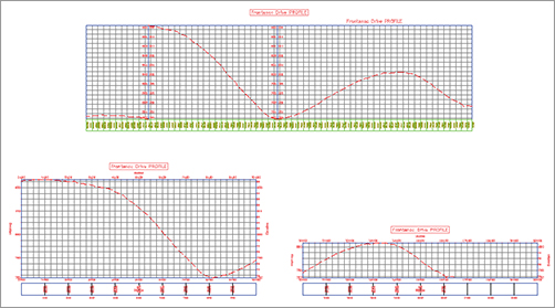
The gapped profile views are the two profile views on the bottom of the screen and, just like the staggered profile view, show the entire alignment from start to finish. Unlike the staggered view, however, the gapped view is separated by a “gap” into two views. In addition, the gapped views are independent of each other so they have their own styles, properties, and labeling associated with them, making them useful when you don’t want a view to show information that is not needed on a particular section. This is also the primary way to create divided profile views for sheet production.
Note that when using the Create Multiple Views option, every profile view is the full length as defined in the wizard, even if the alignment is not that long.
Creating Stacked Profile Views
In some parts of the United States, a three-line profile view is a common requirement. In this situation, the centerline is displayed in a central profile view, with left and right offsets shown in profile views above and below the centerline profile view. These are then typically used to show top-of-curb design profiles in addition to the centerline design. In this exercise, you look at how the Create Profile View wizard makes generating these views a simple process:
1. Open the StackedProfiles.dwg file. This drawing has sampled profiles for the Cabernet Court alignment at center as well as left and right offsets.
2. Change to the Home tab and select Profile View Create Profile View to display the Create Profile View wizard.
3. Select Cabernet Court from the Select Alignment drop-down list.
4. Check the Show Offset Profiles By Vertically Stacking Profile Views option on the General page of the wizard.
5. Click the Stacked Profile text on the left side of the wizard (it’s a hyperlink) to jump to the Stacked Profile step; the page looks like Figure 7-54.
Figure 7-54: Setting up stacked profile views
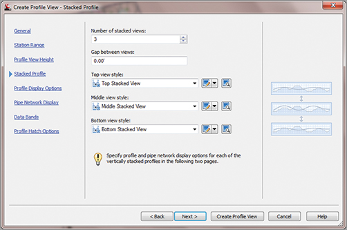
6. Set the style for each view as shown in Figure 7-54 and click Next.
7. Toggle the Draw option for the first profile (EG – Surface (13)) as shown in Figure 7-55. Note that Middle View - [1] is currently selected in the Select Stacked View To Specify Options For list box. Also note that your EG Surface numbers may not be the same as the example.
Figure 7-55: Setting the stacked view options for each view
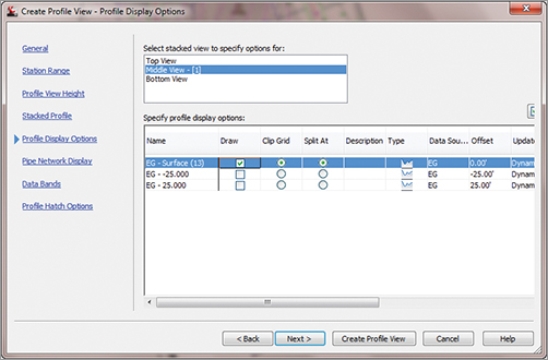
8. Click Top View in the Select Stacked View To Specify Options For list box, and then toggle on the EG - - 25.000 profile (the second profile listed). Note the two hyphen (-) symbols because of the naming template that ships in Civil 3D. This is the left-hand offset.
9. Click Bottom View in the Select Stacked View To Specify Options For list box, and then toggle on the EG - 25.000 profile (the third profile listed). This is the right-hand offset.
10. Click the Create Profile View button, and snap to the center of the circle to the southeast of the site as a pick point. Your result should look similar to Figure 7-56.
Figure 7-56: Completed stacked profiles

The styles for each profile can be adjusted, as can the styles for each profile view. The stacking here simply automates a process that many users found tedious. Once you have created layout profiles, they can also be added to these views by editing the profile view properties.