
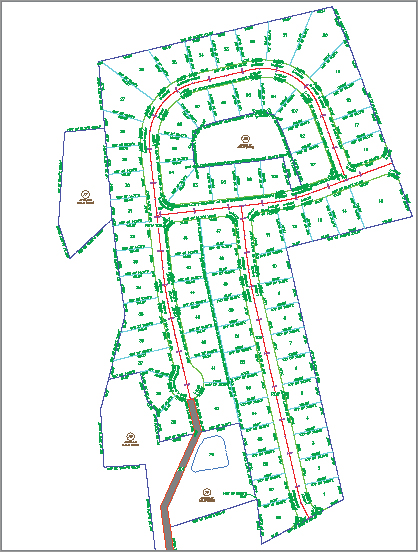
Although parcels are used for much more than just subdivision lots, most parcels you create will probably be used for concept plans, record plats, and other legal subdivision plans. These plans, such as the one shown in Figure 5-57, almost always require segment labels for bearing, distance, direction, crow’s feet, and more.
Figure 5-57: A fully labeled site plan
Labeling Multiple Parcel Segments
The following exercise will teach you how to add labels to multiple parcel segments:
1. Open the SegmentLabels.dwg file, which you can download from this book’s web page. Note that this drawing contains many subdivision lot parcels.
2. Switch to the Annotate tab, and select Add Labels from the Labels & Tables panel on the Annotate tab.
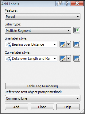
3. In the Add Labels dialog, select Parcel, Multiple Segment, Bearing Over Distance, and Delta Over Length And Radius from the drop-down menus in the Feature, Label Type, Line Label Style, and Curve Label Style selection boxes, respectively, as shown in Figure 5-58.
Figure 5-58: The Add Labels dialog
4. Click Add.
5. At the Select parcel to be labeled by clicking on area label: prompt, pick the area label for Parcel 1.
6. At the Label direction [CLockwise/COunterclockwise]<CLockwise>: prompt, press ↵ to accept the default and again to exit the command.
7. Each parcel segment for Parcel 1 should now be labeled. Continue picking Parcels 2 through 15 in the same manner. Note that segments are never given a duplicate label, even along shared lot lines.
8. Press ↵ to exit the command.
The following exercise will show you how to edit and delete parcel segment labels:
1. Continue working in the SegmentLabels.dwg file.
2. Zoom in on the label along the frontage of Parcel 8 (see Figure 5-59).
Figure 5-59: The label along the frontage of Parcel 8

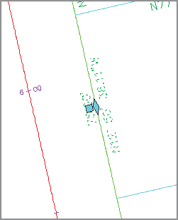
3. Select the label. You’ll know your label has been picked when you see a diamond-shaped grip at the label midpoint (see Figure 5-60).
Figure 5-60: A diamond-shaped grip appears when the label has been picked.
4. Once your label is picked, right-click over the label to bring up the context menu.
5. Select Flip Label from the context menu. The label flips so that the bearing component is on top of the line and the distance component is underneath the line.
6. Select the label again, right-click, and select Reverse Label. The label reverses so that the bearing now reads NW instead of SE.
7. Repeat steps 3 through 6 for several other segment labels, and note their reactions.
8. Select any label. Once the label is picked, execute the AutoCAD Erase tool or press the Delete key. Note that the label disappears.
Labeling Spanning Segments
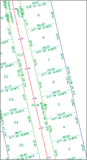
Spanning labels are used where you need a label that spans the overall length of an outside segment, such as the example in Figure 5-61.
Figure 5-61: A spanning label
Spanning labels require that you use the appropriate vertices as discussed in detail in a previous section. Spanning labels have the following requirements:
- Spanning labels can only span across split-created vertices. Natural vertices will interrupt a spanning length.
- Spanning label styles must be composed to span the outside segment.
- Spanning label styles must be composed to attach the desired spanning components (such as length and direction arrow) on the outside segment (as shown previously in Figure 5-61), with perhaps a small offset.
Once you’ve confirmed that your geometry is sound and your label is properly composed, you’re set to span. The following exercise will teach you how to add spanning labels to single-parcel segments:
1. Continue working in the SegmentLabels.dwg file.
2. Zoom in on the outer parcel segment that runs from Parcel 1 through Parcel 10.
3. Change to the Annotate tab and select Add Labels Parcel Add Parcel Labels from the Labels & Tables panel.
4. In the Add Labels dialog, select Single Segment, (Span) Bearing And Distance With Crow’s Feet, and Delta Over Length And Radius from the drop-down menus in the Label Type, Line Label Style, and Curve Label Style selection boxes, respectively.
5. Click Add.
6. At the Select label location: prompt, pick somewhere near the middle of the outer parcel segment that runs from Parcel 1 through Parcel 10.
A label that spans the full length between natural vertices appears (see Figure 5-61).
Flip It, Reverse It
If your spanning label doesn’t seem to work on your first try and you’ve followed all the spanning label guidelines, try flipping your label to the other side of the parcel segment, reversing the label, or using a combination of both flipping and reversing.
Adding Curve Tags to Prepare for Table Creation
Surveyors and engineers often make segment tables to simplify plan labeling, produce reports, and facilitate stakeout. Civil 3D parcels provide tools for creating dynamic line and curve tables, as well as a combination of line and curve tables.
Parcel segments must be labeled before they can be used to create a table. They can be labeled with any type of label, but you’ll likely find it to be best practice to create a tag-only style for segments that will be placed in a table.
The following exercise will teach you how to replace curve labels with tag-only labels, and then renumber the tags:
1. Continue working in the SegmentLabels.dwg file. Note that the labels along tight curves, such as the cul-de-sac, would be better represented as curve tags.
2. Change to the Annotate tab. Select Add Labels Parcel Add Parcel Labels from the Labels & Tables panel.
3. In the Add Labels dialog, select Replace Multiple Segment, Bearing Over Distance, and Spanning Curve Tag Only from the drop-down menus in the Label Type, Line Label Style, and Prop selection boxes, respectively.
4. At the Select parcel to be labeled by clicking on area label or [CLockwise/COunterclockwise]<CLockwise>: prompt, pick the area label for Parcel 1. Note that the line labels for Parcel 1 are reset and the curve labels convert to tags.
5. Repeat step 4 for Parcels 2 through 15. Press ↵ to exit the command.
Now that each curve label has been replaced with a tag, it’s desirable to have the tag numbers be sequential. The following exercise will show you how to renumber tags:
1. Continue working in the SegmentLabels.dwg file.
2. Zoom into the curve on the upper-left side of Parcel 11 (see Figure 5-62). Your curve may have a different number from the figure.
Figure 5-62: Curve tags on Parcel 11


3. Select a parcel and select Renumber Tags from the Labels & Tables panel.
4. At the Select label to renumber tag or [Settings]: prompt, type S, and then press ↵.
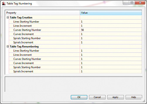
5. The Table Tag Numbering dialog appears (see Figure 5-63). Change the value in the Curves Starting Number selection box to 1. Click OK.
Figure 5-63: The Table Tag Numbering dialog
6. Click each curve tag in the drawing at the Select label to renumber tag or [Settings]: prompt. The command line may say Current tag number is being used, press return to skip to next available or [Create duplicate], in which case you should press ↵ to skip the used number. When you’re finished, press ↵ to exit the command.
Creating a Table for Parcel Segments
The following exercise demonstrates how to create a table from curve tags:
1. Continue working in the SegmentLabels.dwg file. You should have several curves labeled with the Prop label.
2. Select a parcel and choose Add Curve under the Add Tables from the Labels & Tables panel.
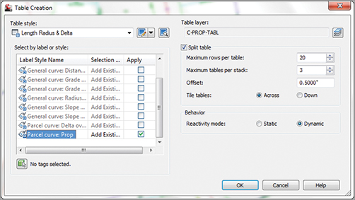
3. In the Table Creation dialog, select Length Radius & Delta from the drop-down menu in the Table Style selection box. In the Selection area of the dialog, select the Apply check box for the Parcel Curve: Prop entry under Label Style Name. Keep the default values for the remaining options. The dialog should look like Figure 5-64. Click OK.
Figure 5-64: The Table Creation dialog
4. At the Select upper left corner: prompt, pick a location in your drawing for the table. A curve table appears, as shown in Figure 5-65.
Figure 5-65: A curve table
