
A point cloud is a huge bunch of 3D points, usually collected by laser scanner or LiDAR (Light Detection and Ranging). In a geographic information system, or GIS, point clouds are often used as a source for a digital elevation model (DEM). The technology has gotten less expensive and more accurate over the last few years, allowing LiDAR to quickly take over from traditional methods of collecting photogrammetry data.
Let Point Clouds Reign!
Point clouds in many formats can be imported to Civil 3D. The most common format is the LAS file. This binary format is a public format and at minimum contains X, Y, and Z data. LAS data can also include the following:
- Coordinate system of scanned area.
- Color; true color on RGB format.
- Intensity; LiDAR depends on lasers bouncing off objects and back to the scanning device. The intensity refers to the strength of the returned information. This value directly relates to the material from which the laser is bouncing. For example, concrete will have a stronger intensity than grass.
- Classification; this will be a number, most frequently between 0 and 9, that categorizes points based on material (i.e., ground, vegetation, or buildings).
For more information on the LAS standard, visit www.asprs.org.
Civil 3D can import a point cloud and use it in several ways. For instance, a laser scan of a bridge can be imported and placed for reference when designing a road through an existing abutment. In the example that follows, we will convert LiDAR data into a Civil 3D surface. It is important to note that point clouds often contain millions of points and require a beefy computer (and a little patience on your part) to process.
Importing a Point Cloud
A typical point cloud contains millions of points. These large files are kept external to Civil 3D in a point cloud database. After the LAS has been imported, the data is passed to three files: PRMD, IATI, and ISD. The ISD contains the points themselves and is the only file needed by CAD if the point cloud would need to be recreated or used in base AutoCAD. By default these files get created in the same directory as the DWG but can be changed when importing the information (Figure 4-54).
Figure 4-54: Create Point Cloud wizard

If the point cloud you are working with contains coordinate system information (as all the examples in this book do), the software will automatically convert the point cloud to the units and coordinate system of the drawing. For the exercises in this chapter, it does not matter whether you choose the Metric template or the Imperial template.
Civil 3D may take a long time to process these files, and you must ensure you have sufficient disk space to store them, as you will find in the following exercise:
1. Start a new file by using the default Civil 3D template of your choice. Save the file before proceeding as Point Cloud.dwg.
2. Select the Point Clouds collection on the Prospector tab of Toolspace and right-click.
3. Select Create Point Cloud from the menu to launch the Create Point Cloud wizard shown in Figure 4-54.
4. Set the name of the Point Cloud to Serpent Mound. Set Point Cloud Style to Elevation Ranges, as shown in Figure 4-54, and click the Next button. The Source Data page is displayed, as shown in Figure 4-55.
Figure 4-55: The Source Data page

5. Using the white plus sign, select Serpent Mound.las. This is a large (90 megabytes) file containing roughly 1.4 million points and may require a minute or two to process. Click the Next button to display the summary page, as shown in Figure 4-56.
Figure 4-56: The summary page

6. Accept the defaults as shown in Figure 4-56 and click Finish to process the point cloud. If the New Point Cloud Database – Processing In Background dialog appears, click Close to dismiss it. The point cloud database is processed in the background. When complete, a portion of a bounding box outlining a portion of the point cloud is displayed in the center of the screen. You must leave this drawing open to complete the next exercise.
Working with Point Clouds
Once the point cloud is visible in your drawing, you’ll want to follow a few rules of thumb to prevent performance problems. The key-in POINTCLOUDDENSITY controls what percentage of the full point cloud displays on the screen at once. You can also access this value using a slider bar in the context Ribbon. However, it is easier to hit the percentage you want on the first try if you use the key-in. The lower this value, the fewer points are visible; hence the easier it will be to navigate your drawing. The POINTCLOUDDENSITY value does not have any effect on the number of points used when generating a surface model.
When you are changing view directions on a point cloud, we recommend that you use preset views and named views to flip around the object. The orbit commands should not be used, as they are a surefire way to max out your computer’s RAM.
If you used the default template, your surface will be located on the V-SITE-SCAN layer. We suggest that you freeze the layer if you do not need to see the point cloud. Use Freeze instead of Off for layer management so the point cloud is not accounted for during pan, zoom, and regen operations (this is true for all AutoCAD objects, but it makes a huge difference when working with point clouds).
Creating a Point Cloud Surface
By specifying either an entire point cloud or a small region of a point cloud, you can create a new TIN surface in your drawing. Any changes to the point cloud object will render the surface definition out of date. In the following exercise, a new TIN surface is created from the point cloud previously imported:
1. Continue using the Point Cloud.dwg file.
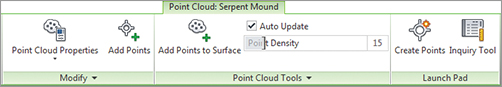
2. Select the bounding box representing the point cloud to display the Point Cloud context tab as shown in Figure 4-57.
Figure 4-57: The Point Cloud context menu
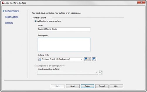
3. Select the Add Points To Surface command, as shown in Figure 4-57, to display the Add Points To Surface wizard, as shown in Figure 4-58. Name the surface Serpent Mound South. Leave the style set to the default.
Figure 4-58: The Add Points To Surface wizard
4. Click Next and the Region Options page is displayed, as shown in Figure 4-59. Choose the Window radio button, and click Define Region In Drawing.
Figure 4-59: The Region Options page

5. Define the region by creating a window around the southern half of the point cloud. Click Next to see the summary page and click Finish. Your results will look similar to those in Figure 4-60.
Figure 4-60: Click Finish on the summary page.
