
You can create points many ways, using the Points menu in the Create Ground Data panel on the Home tab. Points can also be imported from text files or external databases or converted from AutoCAD, Land Desktop, or SoftDesk point objects.
Point Settings
Point settings are our first glimpse at what is known as command settings. All Civil 3D objects have command settings tucked away in the Settings tab of Toolspace. In the case of points, it is handy to have these settings readily available for on-the-fly modifications. Whether or not the changes you make on-the-fly are remembered the next time you create points depends on your template settings (see Chapter 19 for more information on feature settings in the template).
Access the Create Points toolbar by going to the Home tab, and in the Create Ground Data panel, select Points Point Creation Tools. Expand the toolbar by clicking the chevron button on the far-right side.
Default Layer
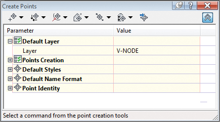
For most Civil 3D objects, the object layer is established in the drawing settings. In the case of points, the default object layer is set in the command settings for point creation and can be changed in the Create Points dialog (see Figure 3-3).
Figure 3-3: Verify the point object layer before creating points.
Prompt for Elevations, Names, and Descriptions
When creating points in your drawing, you have the option of being prompted for elevations, names, and descriptions (see Figure 3-4). In many cases, you’ll want to leave these options set to Manual. The command line will ask you to assign an elevation, name, and description for every point you create.
Figure 3-4: You can change the elevation, point name, and description settings from Manual to Automatic.
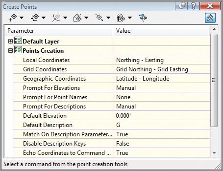
If you’re creating a batch of points that have the same description or elevation, you can change the Prompt toggle from Manual to Automatic and then provide the description and elevation in the default cells. For example, if you’re setting a series of trees at an elevation of 10’, you can establish settings as shown in Figure 3-5.
Figure 3-5: Default settings for placing tree points at an elevation of 10’

Note that these settings only apply to points created from this toolbar. The settings do not affect the elevation or description of points imported from a file.
What’s in a Name?
Users often confuse a point’s name with description. The name is a unique, alphanumeric sequence that can be used in lieu of a point number. Description refers to the all-important code given to a point out in the field. Most survey software today does not use alphanumeric point identification, so this option is usually set to None in Civil 3D. If you do have a point file that uses a name instead of point number, you will need to create a custom point format, as described later in this chapter.
Importing Points from a Text File
One of the most common means of creating points in your drawing is to import an external text file (see Figure 3-6).
Figure 3-6: The Import Points and the Point File Formats – Create Group dialogs
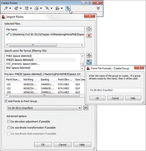
To add a file to your Import Points dialog, click the plus sign to browse. You can add multiple files at once if they are in the same point format (i.e., PNEZD (comma delimited)). The import process supports most text formats as well as Microsoft Access Database (MDB) files.
When your file is listed in the top of the dialog box, a green check mark will indicate that Civil 3D can parse the information. Be careful, though, as Civil 3D does not know the difference between a Northing and an Easting or a point number and an elevation. You still need to select the correct file format.
The file format filter is there to help you. Civil 3D recognizes how the file is delimited (i.e., tab, comma, space) and only shows you the formats that apply. If you don’t want the help, you can turn the filtering off by clicking the Filter icon.
If the file format you need is not available, or you wish to use the adjustment and transformation capabilities, you can do so by clicking the Manage Formats button.
You can make an elevation adjustment if the point file contains additional columns for thickness, Z+, or Z–. You can add these columns as part of a custom format. See the Civil 3D 2012 Users Guide section “Using Point File Format Properties to Perform Calculations” for more details.
You can perform a coordinate system transformation if a coordinate system has been assigned both to your drawing (under the drawing settings) and as part of a custom point format. In this case, the program can also do a coordinate data expansion, which calculates the latitude and longitude for each point.
A common use of the formats is to create a point file format for importing a name-based point file. In the following example, you will create a new file format to accommodate names (instead of point numbers):
1. Open the Import Points dialog box and click the Manage Points icon. (You can also access this functionality by going to the Settings tab and choosing Point and then Point File Formats.)
2. Click New, choose the User Point File option, and click OK.
3. Name the format Name-NEZD. Toggle on the Delimited By option and place a comma in the field.
4. Click the first <unused> column heading. Select Name from the Column Name drop-down menu and click OK.
5. Click the next <unused> column and select Northing from the Column Name drop-down. Leave Invalid Indicator and Precision fields as default and click OK.
6. Repeat the process for Easting, Point Elevation, and Raw Description.
7. To test the format, click Load. Select the file Test Format.txt and click Open.
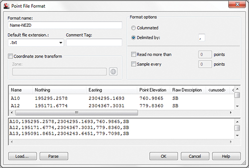
8. Click Parse. If the format has been created successfully, you will see the file preview as shown in Figure 3-7.
Figure 3-7: A completed and tested new point file format
9. Click OK to complete the format and close the Point File Format dialog. Dismiss the Import Points dialog. The new file format will remain in case you need it.
Importing a Text File of Points
In this exercise, you’ll learn how to import a TXT file of points into Civil 3D:
1. Open the Mastering Points.dwg file, which you can download from this book’s web page at www.sybex.com/go/masteringcivil3d2012.
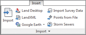
2. Open the Import Points dialog by selecting Points From File in the Import panel of the Insert tab.
3. Change the Format field to PNEZD (Comma Delimited).
4. Click the file folder’s plus (+) button to the right of the Source File field, and navigate out to locate the Mastering_C3D_Points.txt file.
5. Click the Create Point group icon. Name the point group Survey 05-05-2011 and click OK.
6. Leave all the other boxes unchecked.
7. Click OK. You may have to use Zoom Extents to see the imported points. (Hint: Double-click your middle mouse wheel for zooming extents.)
LandXML and Points: A Match Made in Heaven
LandXML is a file format specifically made to share the type of data Civil 3D and its counterparts create. For points, it works particularly well, since it will also carry point group information. Import LandXML files from the Import panel on the Insert tab. You’ll learn much more about LandXML in Chapter 17, “Interoperability.”
Thinking Ahead: Assigning Point Numbers
Point numbers are assigned using the Point Identity settings in the Create Points dialog or the point file from which they originated. To list available point numbers, enter ListAvailablePointNumbers on the command line, or select any point to open the context-sensitive Ribbon and choose COGO Point Tools List Available Point Numbers.
Converting Points from Land Desktop, SoftDesk, and Other Sources
Civil 3D contains several tools for migrating legacy point objects to the current version. The best results are often obtained from an external point list, such as a text file, LandXML, or an external database. However, if you come across a drawing that contains the original Land Desktop, SoftDesk, AutoCAD, or other types of point objects, tools and techniques are available to convert those objects into Civil 3D points.
A Land Desktop point database (the Points.mdb file found in the COGO folder in a Land Desktop project) can be directly imported into Civil 3D in the same interface in which you’d import a text file.
Land Desktop point objects, which appear as AECC_POINTs in the AutoCAD Properties palette, can also be converted to Civil 3D points (see Figure 3-8). Upon conversion, this tool gives you the opportunity to assign styles, create a point group, and more.
Figure 3-8: The Convert Land Desktop Points option (left) opens the Convert Autodesk Land Desktop Points dialog (right).
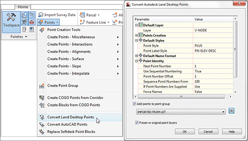
Occasionally, you’ll receive AutoCAD point objects drawn at elevation from aerial topography information or other sources. It’s also not uncommon to receive SoftDesk point blocks from outside surveyors. Both of these can be converted to or replaced by Civil 3D points by using the Points drop-down on the Create Ground Data panel of the Home tab (see Figure 3-8).
Using AutoCAD Attribute Extraction to Convert Outside Program Point Blocks
Occasionally, you may receive a drawing that contains point blocks from a third-party program such as Eagle Point or Carlson. These point blocks may look similar to SoftDesk point blocks, but the block attributes may have been rearranged and you can’t convert them directly to Civil 3D points using Civil 3D tools.
Whenever possible, your best course of action would be to request the source survey in text format or LandXML. If that is not possible, the exercise that follows will pull the data you need without losing the information from the attributes.
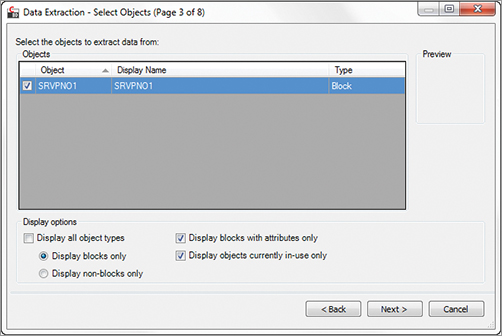
1. Open the file Mystery Plat.dwg. First, examine the blocks you are given to determine the names of the blocks with which you are working. A glance at AutoCAD properties will give you an idea of your block name and what attributes you are extracting. In this example, we are seeing Carlson survey blocks, which use the SRVPNO1 as an anchor for its attributes.

2. Use the Data Extraction tool by typing EATTEXT in the command line to launch the Data Extraction Wizard.
3. Select the radio button to create a new data extraction and click Next. The Save Extraction As page appears, prompting you to name and save this extraction. Give the extraction a meaningful name, and save it in the appropriate folder. Click Next.
4. Confirm that the drawings to be scanned for attributed blocks are on the list:

5. In the Select Objects screen of the Data Extraction Wizard, uncheck Display All Object Types. Check Display Blocks With Attributes Only and Display Objects Currently In-Use Only; doing so will filter out most unneeded blocks. Eliminate the other types of attributed blocks by deselecting their boxes. Click Next.
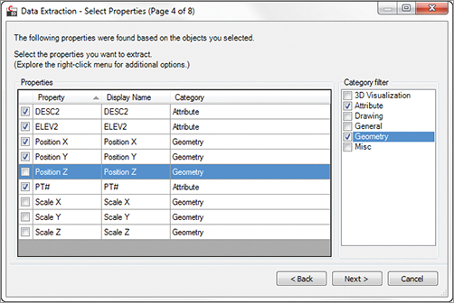
6. On the next screen, select these properties: the point number (PT#), elevation (ELEV2), and description (DESC2), as well as Position X and Position Y. In this case, we are relying on the attribute ELEV2 instead of the Position Z; you do not need both. Click Next.
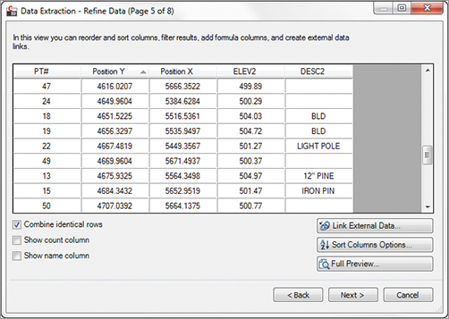
7. On the Refine Data screen, rearrange the columns into a PNEZD format by clicking and dragging the column headers into place. Uncheck Show Count Column and Show Name Column. Click Next.
8. On the Choose Output screen, set Output Data to External File, and save your extraction as an CSV file in a logical place.
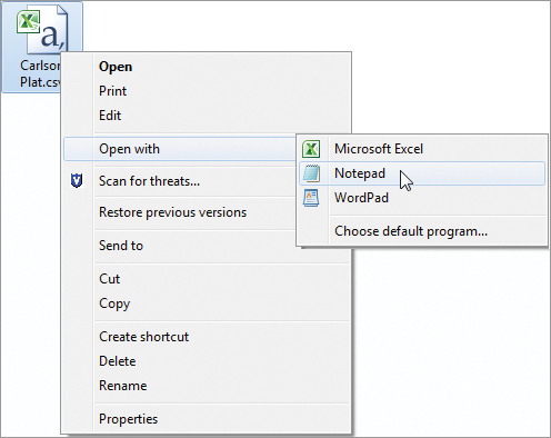
9. Locate the file in Windows. Right-click on it and select Open With Notepad. Remove the first line of text (the header information). Save and close the file.
10. In a drawing that contains your Civil 3D styles, use the Import Points tool in the Create Points dialog to import the CSV file.
Converting Points
In this exercise, you’ll convert Land Desktop point objects and AutoCAD point entities into Civil 3D points:
1. Open the Convert LDT Points.dwg file, which you can download from this book’s webpage.
2. Use the List command or the AutoCAD Properties palette to confirm that most of the objects in this drawing are AECC_POINTs, which are points from Land Desktop. Also, note a cluster of cyan-colored AutoCAD point objects in the western portion of the site.
3. Run the Land Desktop Point Conversion tool by switching to the Home tab and choosing Points Convert Land Desktop Points. Note that the Convert Autodesk Land Desktop Points dialog allows you to choose a default layer, point creation settings, and styles.
4. Place a check mark next to Add Points To Point Group. Click the Create A New Point Group button. Name the group Converted from LDT and click OK.
5. Click OK to complete the conversion process. Civil 3D scans the drawing looking for Land Desktop point objects.
6. Once Civil 3D has finished the conversion, zoom in on any of the former Land Desktop points. The points should now be AECC_COGO_POINTs in both the List command and in the AutoCAD Properties palette, confirming that the conversion has taken place. The Land Desktop points have been replaced with Civil 3D points, and the original Land Desktop points are no longer in the drawing.
7. In Prospector, expand the Point Groups category. Notice there is a symbol indicating that the point group needs to be updated. Right-click on Point Groups and select Update.
8. Zoom in on the cyan AutoCAD point objects.
9. Run the AutoCAD Point Conversion tool by choosing Points Convert AutoCAD Points from the Home tab.
10. The command line reads Select AutoCAD Points. Use a crossing window to select all the cyan-colored AutoCAD points.
11. At the command-line prompt, enter a description of GS (Ground Shot) for each point.
12. Zoom in on one of the converted points, and confirm that it has been converted to a Civil 3D point. Also, note that the original AutoCAD points have been erased from the drawing.
Getting to Know the Create Points Dialog
In Civil 3D 2012, you can find point-creation tools directly under the Points drop-down on the Create Ground Data panel of the Home tab as well as in the Create Points toolbar. The toolbar is modeless, which means it stays on your screen even when you switch between tasks. Figure 3-9 shows the toolbar with the point creation methods labeled.
Figure 3-9: The Create Points toolbar

As you place points using these tools, a few general rules apply to all of them. If you place a point on an object with elevation, the point will automatically inherit the elevation of the object. If you use the surface options, the point will automatically inherit the elevation of the surface you choose.
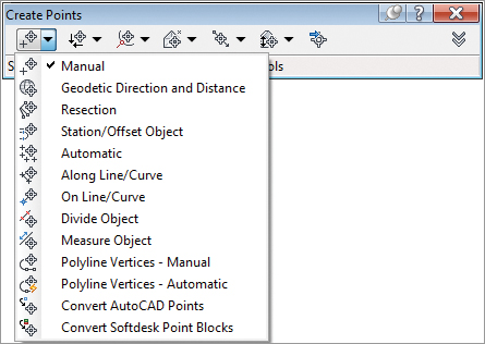
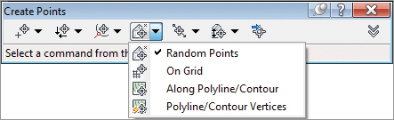
Miscellaneous Point-Creation Options The options in the Miscellaneous category are based on manually selecting a location or on an AutoCAD entity, such as a line, pline, and so on. Some common examples include placing points at intervals along a line or polyline, as well as converting SoftDesk points or AutoCAD entities (see Figure 3-10).
Figure 3-10: Miscellaneous point-creation options
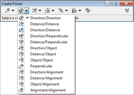
Intersection Point-Creation Options The options in the Intersection category allow you to place points at a certain location without having to draw construction linework. For example, if you needed a point at the intersection of two bearings, you could draw two construction lines using the Bearing Distance transparent command, manually place a point where they intersect, and then erase the construction lines. Alternatively, you could use the Direction/Direction tool in the Intersection category (see Figure 3-11).
Figure 3-11: Intersection point-creation options
Alignment Point-Creation Options The options in the Alignment category are designed for creating stakeout points based on a road centerline or other alignments. You can also set Profile Geometry points along the alignment using a tool from this menu. See Figure 3-12.
Figure 3-12: Alignment point-creation options

Automatic – Object: Unmasking the Mystery
The description option in the point settings, Automatic – Object, can only be used when placing points along an alignment. For example, when placing points using the At Geometry Points option, the point will inherit the alignment’s name, the station value of the point, and the type of geometry as its description.
For all other point placement options, Automatic – Object will behave exactly the same as Automatic.
Surface Point-Creation Options The options in the Surface category let you set points that harvest their elevation data from a surface. Note that these are points, not labels, and therefore aren’t dynamic to the surface. You can set points manually, along a contour or a polyline, or in a grid. See Figure 3-13.
Figure 3-13: Surface point-creation options
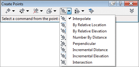
Interpolation Point-Creation Options The Interpolation category lets you fill in missing information from survey data or establish intermediate points for your design tasks. For example, suppose your survey crew picked up centerline road shots every 100’, and you’d like to interpolate intermediate points every 25’. Instead of doing a manual slope calculation, you could use the Incremental Distance tool to create additional points (see Figure 3-14).
Figure 3-14: The Interpolation point-creation options
Another use would be to set intermediate points along a pipe stakeout. You could set a point for the starting and ending invert, and then set intermediate points along the pipe to assist the field crew.
Slope Point-Creation Options The Slope category allows you to set points between two known elevations by setting a slope or grade. Similar to the options in the Interpolation and Intersection categories, these tools save you time by eliminating construction geometry and hand calculations (see Figure 3-15).
Figure 3-15: Slope point-creation options

Creating Points
In this exercise, you’ll learn how to create points along a parcel segment and along a surface contour:
1. Open Mastering Point Creation.dwg, which you can download from this book’s webpage. Note the drawing includes an alignment, a series of parcels, and an existing ground surface.
2. Open the Create Points dialog by selecting Points Point Creation Tools in the Create Ground Data panel on the Home tab.
3. Click the chevron icon on the right to expand the dialog.
4. Expand the Points Creation option. Change the Prompt For Elevations value to None and the Prompt For Descriptions value to Automatic by clicking in the respective cell, clicking the down arrow, and selecting the appropriate option. Enter LOT for Default Description (see Figure 3-16). This will save you from having to enter a description and elevation each time. Because you’re setting stakeout points for rear lot corners, you will disregard elevation for now.
Figure 3-16: Point-creation settings in the Create Points dialog

5. Select the Automatic tool under the Miscellaneous category (the first button on the top left of the Create Points dialog).
6. Select all five of the blue property lines in the drawing. Press ↵.
7. Press Esc to exit the command. A point is placed at each property corner and at the endpoints of each curve.
8. Select the Measure Object tool under the Miscellaneous category to set points along the boundary for Property 10. After selecting the object, this tool prompts you for starting and ending stations (press ↵ twice to accept the measurements), offset (press ↵ to accept 0), and an interval (enter 25). Press Esc to exit the command. A point is placed at 25′ intervals along the property boundary.
9. Next you’ll experiment with the Direction-Direction option from the Intersection Point flyout. Click the Direction-Direction icon and click the southeast endpoint of the “floating” parcel line. Click the opposite endpoint to establish the direction of the line. Press ↵ to specify a zero offset.
10. Starting from the southeastern corner of Property 6, establish the second direction by clicking each endpoint of the segment. Press ↵ to specify a zero offset. A point is generated where the two lines would intersect if they were to be extended. Press Esc to exit the command.
11. In the point settings, change Prompt For Descriptions to Automatic – Object.
12. From the Alignments flyout, choose At Geometry Points. Select the green centerline alignment. You are now prompted for a profile. Select Layout (1) from the drop-down and click OK.
13. Press ↵ twice to confirm the station values along which you will place points. Press Esc to exit the command. You should now see points with the name of the alignment and station values.
14. Return to the Point Settings options and change Prompt For Elevations to Manual and Default Description to EG. The next round of points you’ll set will be based on the existing ground elevation.
15. Select the Along Polyline/Contour tool in the Surface category to create points every 25’ along the driveway near HOUSE2.
16. Experiment with the plethora of point placement tools available to you!