In many cases, the “Create Line By…” commands in the Draw panel are the standard AutoCAD Line commands combined with the appropriate transparent commands.
A transparent command behaves somewhat similarly to an osnap command. You can’t click the Endpoint button and expect anything to happen—you must be active inside another command, such as a line, an arc, or a circle command.
The same principle works for transparent commands. Once you’re active in the Line command (or any AutoCAD or Civil 3D drawing command), you can choose the Bearing Distance transparent command and complete your drawing task using a bearing and distance.
As stated earlier, the transparent commands can be used in any AutoCAD or Civil 3D drawing command, much like an osnap. For example, you can be actively drawing an alignment and use the Northing/Easting transparent command to snap to a particular coordinate, and then press Esc once and continue drawing your alignment as usual.
While a transparent command is active, you can press Esc once to leave the transparent mode but stay active in your current command. You can then choose another transparent command if you’d like. For example, you can start a line using the Endpoint osnap, activate the Angle Distance transparent command, draw a line-by-angle distance, and then press Esc, which takes you out of angle-distance mode but keeps you in the Line command. You can then draw a few more segments using the Point Object transparent command, press Esc, and finish your line with a Perpendicular osnap.
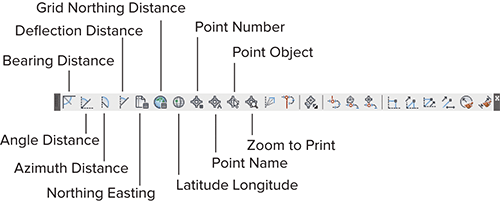
You can activate the transparent commands using keyboard shortcuts or using the Transparent Commands toolbar. Be sure you include the Transparent Commands toolbar (shown in Figure 1-50) in all your Civil 3D and survey-oriented workspaces.
Figure 1-50: The Transparent Commands toolbar

The six profile-related transparent commands will be covered in Chapter 7, “Profiles and Profile Views.”
Standard Transparent Commands
The transparent commands shown in Table 1-1 behave identically to their like-named counterparts from the Draw panel (discussed earlier in this chapter). The difference is that you can call up these transparent commands in any appropriate AutoCAD or Civil 3D draw command, such as a line, polyline, alignment, parcel segment, feature line, or pipe-creation command.
Table 1-1: The transparent commands
| Tool icon | Menu command |
|
|
Angle Distance |
|
|
Bearing Distance |
|
|
Azimuth Distance |
|
|
Deflection Distance |
|
|
Northing Easting |
|
|
Grid Northing Easting |
|
|
Latitude Longitude |
|
|
Point Number |
|
|
Point Name |
|
|
Point Object |
|
|
Zoom To Point |
|
|
Side Shot |
|
|
Station Offset |
Matching Transparent Commands
You may have construction or other geometry in your drawing that you’d like to match with new lines, arcs, circles, alignments, parcel segments, or other entities.
While actively drawing an object that has a radius parameter, such as a circle, an arc, an alignment curve, or a similar object, you can choose the Match Radius transparent command and then select an object in your drawing that has your desired radius. Civil 3D draws the resulting entity with a radius identical to that of the object you chose during the command. You’ll save time using this tool because you don’t have to first list the radius of the original object and then manually type in that radius when prompted by your circle, arc, or alignment tool.
The Match Length transparent command works identically to the Match Radius transparent command except that it matches the length parameter of your chosen object.
