The best design in the universe is not worth anything unless it is labeled properly. Civil 3D labels are smart objects that are dynamically linked to the object they are labeling. Civil 3D labeling is customizable to fit the needs of your design and local requirements.
When talking about labels in Civil 3D, keep in mind that you are not just talking about text. Labels can contain lines and blocks if desired. Label styles control the size, contents, and precision of text. Label styles also control how leaders are applied when the label is dragged away from its initial position. You will even work with some labels that contain no text at all!
Like other settings in Civil 3D, there is a hierarchy that helps the user and the software decide which styles take precedence over other styles. There are also items that can be changed at a drawing-wide level and pushed out to object-level labels. Use this ability with caution, as most labels will use their own layers and behave differently depending on the object it is labeling.
In the first exercise, you will set all labels to use the same initial text style:
1. Open the drawing Label Basics.dwg, which you can download from this book’s web page.
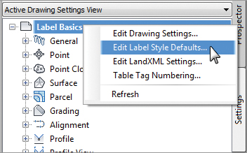
2. From the Settings tab of Toolspace, right-click on the name of the drawing and select Edit Label Style Defaults, as shown in Figure 19-58.
Figure 19-58: Accessing the global text settings
3. Expand the Label category and change Text Style to Arial. Click the arrow in the Child Override column to force all label styles in this drawing to use the same text, as shown in Figure 19-59.
Figure 19-59: Label placement options as shown at the drawing level
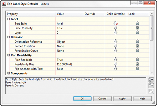
4. Do not make any more changes to this dialog, but examine the various options and settings. Click OK.
The options shown in Figure 19-59 include the following:
Text Style This option refers to the base AutoCAD text style used in the label.
Layer This option defines the layer on which the components of a label are inserted, not the layer on which the label itself is inserted. Think of labels as nested blocks. The label (the block) gets inserted on the layer on the basis of the object layers you saw earlier. The components of the label get inserted on the layer that is set here. This means a change to the specified layer can control or change the appearance of the components if you like. However, if you leave the component layers at 0, the overall object layer will control the look, making the object behave more like a traditional block.
Orientation Reference This option controls how text rotation is controlled. Figure 19-60a shows the most common option where the label is aligned with the object. Figure 19-60b shows the text rotated to the view. Even though the view has been rotated, the text still appears parallel with the bottom of the screen. The last, and least used, option for text is the World Coordinate System option, shown in Figure 19-60c. The view is rotated, and the direction of the text rotates with the coordinate system.
Figure 19-60: Orientation reference options set to Object (a), View (b), and World Coordinate System (c)

Forced Insertion This option makes more sense in other objects and will be explored further. The Forced Insertion feature allows you to dictate the insertion point of a label on the basis of the object being labeled. Figure 19-61 shows the effects of the various options on a bearing and distance label.
Figure 19-61: Forced Insertion options shown for parcel segments
Plan Readable When this option is enabled, text maintains the up direction in spite of view rotation. This tends to be the “Ooooh, nice” feature that makes users smile. Rotating 100 labels is a tedious, thankless task, and this option handles it with one click.
Readability Bias This option specifies the angle at which readability kicks in. This angle is measured from the 0 degree of the x-axis that is common to AutoCAD angle measurements. When a piece of text goes past the readable bias angle, the text flips direction to maintain vertical orientation, as shown in Figure 19-62. The default Readability angle is 110. A common desired default is 90.1, which would flip any text just after passing a vertical direction.
Figure 19-62: Plan-readable text shown on contours; note the direction difference between the top grouping and the bottom grouping.

Flip Anchors With Text Most users leave this obscure setting at its default, False, and never give it another thought. Figure 19-63a shows what happens to the text insertion points when this option is set to False and readability kicks in. Notice how the text flips to the bottom of the line it is labeling when this setting is set to True, as shown in Figure19.63b.
Figure 19-63: Flip anchors with text? Best leave this alone!
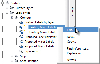
To get into a label style, find the appropriate label type in the Settings tab of Toolspace. Right-click the style you wish to edit (or copy) and select Edit, as shown in Figure 19-64.
Figure 19-64: Entering a label style for editing
Inside the label styles themselves, you will see the same tabs regardless of the object you are labeling.
The General tab (Figure 19-65) has the label-specific version of the options we explored in the previous section.
Figure 19-65: General tab for text placement

The Layout tab (Figure 19-66) is the true heart of any label style. This is where you tell Civil 3D what to label and exactly how that label is to be attached to the feature you are labeling.
Figure 19-66: The Layout tab
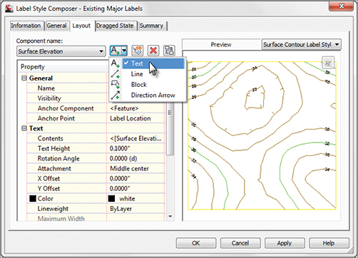
Each label can be made up of several components. A label component can be text, a block, or a line, and the top row of buttons controls the selection, creation, and deletion of these components:
Component Name Choose the component you want to modify from the Component Name drop-down menu. The components are listed in the order in which they were created. Pay attention to which component is active when you make changes to properties on the layout tab. The changes you make to properties will only apply to the active component.

Create Component The Create Component button lets you add new elements to enhance your labels. These components can be text, lines, blocks, ticks, direction arrows, or reference text. The options will vary depending on the object you are labeling. Not every option is available in every label.
The ability to label one object while referencing another (reference text) is one of the most powerful labeling features of Civil 3D. This is what allows you to label a spot elevation for both an existing and a proposed surface at the same time, using the same label. Alignments, COGO points, parcels, profiles, and surfaces can all be used as reference text.
Copy Component The Copy Component button copies the component currently selected in the Component Name drop-down menu. This will be helpful when creating label styles that contain multiple pieces of similar information.
Delete Component The Delete Component button deletes components. Elements that act as the basis for other components can’t be deleted.
Component Draw Order The Component Draw Order button lets you shuffle components up and down within the label. This feature is especially important when you’re using masks or borders as part of the label.
You can work your way down the component properties and adjust them as needed for a label:
Name This option defines the name used in the Component Name drop-down menu and when selecting other components. When you’re building complicated labels, a little name description goes a long way.
Visibility When set to True, this option means the component shows on screen. Why create a component that can’t be seen? There are cool tricks you can do with styles, as you’ll see in the section “Pipe Labels” later in this chapter.
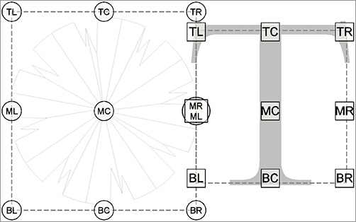
Anchor Component and Anchor Point Use these options to control text placement. Anchor Component lets you tell Civil 3D how text (or other label components) relate to the main object you are labeling. See Figure 19-67 and Figure 19-69 for a graphical explanation of how these options relate to each other. The circles represent anchor points and the squares represent attachment.
Figure 19-67: Closer look at the Layout tab options
Text Height This option determines the plotted height of the label. Text placed by Civil 3D is always annotative. Figure 19-68 shows two viewports showing some COGO points along a road. Even when the viewport scales differ, the text is the same size.
Figure 19-68: Civil 3D text is always annotative.

Rotation Angle, X Offset, and Y Offset These options give you the ability to refine the placement of the component by rotating or displacing the text in an x or y direction. Set your text as close as possible using the anchors and attachments and use the offsets as additional spacing.
Attachment This option determines which of the nine points on the label components bounding box are attached to the anchor point. See Figure 19-69 for an illustration.
Color and Lineweight These options allow you to force the color if desired. It’s a good idea to leave these values set to ByLayer unless you have a good reason to change them.
Figure 19-69: Schematic showing the relationship between anchor points (circles) and attachments (squares)
The final piece of the component puzzle is the Border option. These options are as follows:
Visibility Use this option to turn the border on and off for the component. Remember that component borders shrink to the individual component; if you’re using multiple components in a label, they all have their own borders.
Type This option allows you to select a rectangle, a rounded rectangle (slot), or a circle border. Figure 19-70 shows examples of the three types of borders.
Figure 19-70: Border types shown on various surface label styles

Background Mask This option lets you determine whether linework and text behind this component are masked. This option can be handy for construction notes in place of the usual wipeout tools. The surface labels in Figure 19-70 show the background mask in action.
Gap This option determines the offset from the component bounding box to the outer points on the border. Setting this to half of the text size usually creates a visually pleasing border.
Linetype and Lineweight These options give you control of the border lines.
After working through all the options for the default label placement, you need to set the options that come into play when a label is dragged. To do so, switch to the Dragged State tab, shown in Figure 19-71.
Figure 19-71: The Dragged State tab
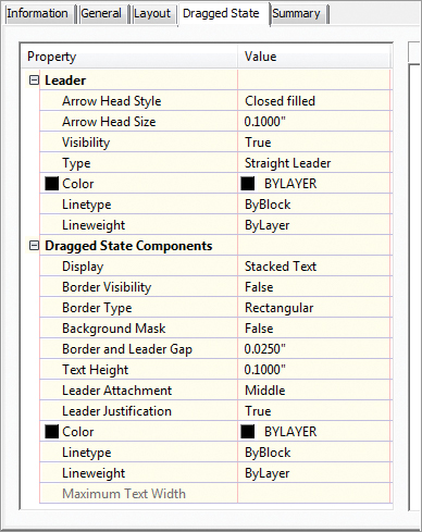
When a label is dragged in Civil 3D, it typically creates a leader, and text is rearranged. The settings that control these two actions appear on this tab. Here are some of the unique options:
Arrow Head Style and Size These options control the tip of the leader. Note that Arrow Head Size also controls the tail size leading to the text object.
Type This option specifies the leader type. Options are Straight Leader and Spline Leader. As of this writing, the AutoCAD multiple leader object can’t be used.
Display This option controls whether components rearrange their placement to a stacked set of components (Stacked Text) or maintain their arrangement as originally composed (As Composed).
Figure 19-72a shows an alignment label as it was originally placed. Figure 19-72b shows the same label in a dragged state with the Stacked Text option set. Figure 19-72c shows the label in a dragged state with the As Composed option set.
Figure 19-72: An alignment label as originally placed (a); Dragged State, Stacked Text (b); and Dragged State, As Composed (c)

Getting to Know the Text Component Editor
Few dialogs in Civil 3D inspire expletives the way the Text Component Editor can. The interface is very logical and will do exactly what you tell it to do—not necessarily what you want it to do. Hopefully, with some explanation you will see the reasoning behind its behavior and master it!
To enter the Text Component Editor, from the Layout tab of any text style, click the ellipsis that pops up when you click in the Text Contents area.

Within the Text Component Editor are two main areas. The left side is where you select what aspect of the Civil 3D object you want to pull into your label. The right side shows what is already in the label.
To modify an existing label, highlight the chunk of text on the right side of the dialog. Civil 3D’s “smart” text will always highlight as a unit. Each of the cryptic codes in the label represents a setting for units, precision, or other ways the text can display. What appears on the left is a decoded list of what is currently part of your label. After making changes, don’t forget to click the arrow to update the information on the right.
Before adding new text to a label, make sure you don’t have any existing text highlighted on the right to avoid overwriting it.
The Properties list shows everything that can be labeled about the item you are working with. The length of the list varies depending on the object. Here you see the available properties for a contour (left) and a pipe network structure (right):

Once you pick what you’d like to label, you will set the units, precision, and any other special rounding or formatting you would like to see.
When everything is set, click the arrow next to the Properties list.
To further fine-tune the text, a Format tab sits inconspicuously behind the Properties list. Use this to add special symbols, or to override the color and text style.
Inevitably, you will forget the arrow that adds or updates the text. You may even click it twice and end up with duplicates! Now that you’ve been given the heads-up you’ll be able to laugh it off, knowing that it happens to even the most seasoned users.
General Note Labels
General Note labels are versatile, non-object-specific labels that can be placed anywhere in the drawing. There are several advantages to using these instead of base-AutoCAD MTEXT. Notes will leader off and scale the same as the rest of your Civil 3D text and, best of all, they can contain reference text.
In the following example, you will create an alternate parcel label that contains reference text:
1. Open the drawing file Example Labels.dwg, which you can download from this book’s web page.
2. From the Settings tab of Toolspace, choose General Label Styles Note. Right-click on Note and select New.
3. On the Information tab, name the style Easement Parcel Text.
4. On the General tab, set Layer to C-PROP-TEXT. Set Orientation Reference to View.
5. On the Layout tab, click the field next to Contents under the Text category. Clicking this will cause an ellipsis button to appear. Click the ellipsis button to enter the Text Component Editor.
6. On the right side of the Text Component Editor, strike out the existing text and replace it with Drainage Easement, as shown in Figure 19-73. Click OK.
Figure 19-73: Entering the Text Component Editor for basic text

7. Back in the Layout tab, set Border Visibility to False.

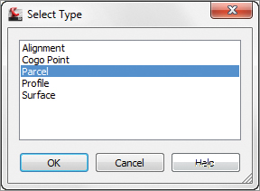
8. Click the flyout next to Create Text Component and select Reference Text. You will be prompted to select the type of reference text, as shown in Figure 19-74. Select Parcel and click OK.
Figure 19-74: Picking the reference type
9. Rename the Reference Text.1 to Parcel Area and make the following changes:
- Set Anchor Component to Text.
- Set Anchor Point to Bottom Center.
- Set Attachment to Top Center.
- Click the Label Text field and enter the Text Component Editor.
10. Remove the existing label text. On the left side of the Text Component Editor, set the Properties drop-down to Parcel Area. Set Unit to Acre. Set Precision to 0.01.
11. When you have set the properties, click the arrow icon to place the text in the right side of the editor. Add ACRES after the coding. The Text Component Editor will resemble Figure 19-75. Click OK.
Figure 19-75: Adding “smart” text to the Text Component Editor

12. You will still have question marks in the preview, but this is completely expected. Click OK to complete the command.
13. On the Annotate tab, click Add Labels. With Feature and Label Type set to Note, change Note Label Style to Easement Text. Click Add.
14. Click in the easement area in the southwest portion of the site. At the prompt Select parcel for label style component Parcel Area:, click the label on parcel 200. Press Esc on your keyboard to finish placing labels. Your completed and placed label should resemble Figure 19-76.
Figure 19-76: Your first label! Referencing parcel area.

Point Label Styles
If you have used other software packages for surveying work, odds are that you controlled point label text with layers, but Civil 3D is different. In Civil 3D, you must control what information is showing next to a point by swapping the label style applied to a group of points.
In the following exercise, you will create a new point label style. Your first point label style will show only Point Number and Description, so you will need to delete the default Elevation component.
1. Open the drawing Point Labels.dwg, which you can download from this book’s web page.
2. From the Settings tab of Toolspace, choose Point Label Styles. Right-click Label Styles and select New.
3. On the Information tab, name the style Point Number & Description.
4. On the General tab, set the layer to V-NODE-TEXT. Leave all other General tab options at their defaults.
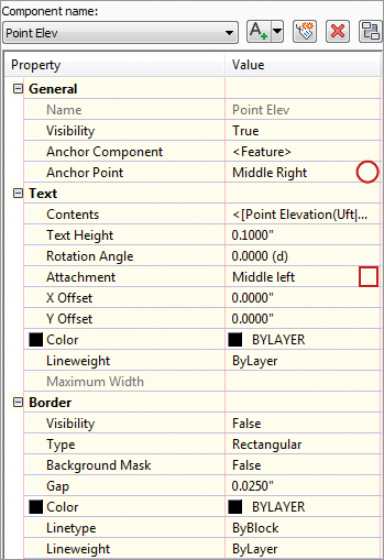
5. On the Layout tab, do the following:
- Set the active component to Point Number. Change the anchor component to <Feature>. Set Anchor Point to Middle Right and set Attachment to Middle Left.
- Change the Active component to Point Elevation. Click the red X to delete this component. You will receive a warning that reads “This label component is used an as anchor in this style or in a child style. Do you want to delete it?” Click Yes.
- Change the active component to Point Description. Change the anchor component to Point Number. Change the anchor point to Middle Right. Change the attachment to Middle Left. Change the X Offset to 0.05″.
- Click OK to complete the label style.
6. In Prospector, locate the point group named TOPO. Right-click on TOPO and select Properties. Set the Point Label style to Point Number & Description. All the points in the group will change to resemble Figure 19-77.
Figure 19-77: Completed point label style
In the previous exercise, you created a simple new label style and made some modifications to the default components. In the following exercise, you will remove all the default components and add Northing and Easting values to the label using the Text Component Editor.
1. Continue working in the drawing Point Labels.dwg.
2. From the Settings tab of Toolspace, choose Point Label Styles. Right-click Label Styles and select New.
3. On the Information tab, name the style Northing & Easting.
4. On the General tab, set the layer to V-NODE-TEXT. Leave all other General tab options at their defaults.
5. On the Layout tab, do the following:
- Click the red X until all three default components are gone. When you are asked about deleting the anchor, click Yes.
- Click the button to create a new text component. Rename the component to N-E. Set the anchor point to Bottom Center. Set the attachment to Top Center.
- Click the Label Text field and enter the Text Component Editor by clicking the ellipsis. Highlight the default label text and delete it by pressing the Delete key on your keyboard.
- From the Properties list, select Northing. Set the Precision to 0.01 (two decimal places).
- Click the arrow to place the text to the right. After the label text, place an N as a static label after the Northing value.
- From the Properties list, select Easting. Set the Precision to 0.01 (two decimal places).
- Click the arrow to place the text to the right. After the label text, place an E as a static label after the Easting value.
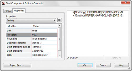
The Text Component Editor will now resemble Figure 19-78.
Figure 19-78: The Northing & Easting label in progress
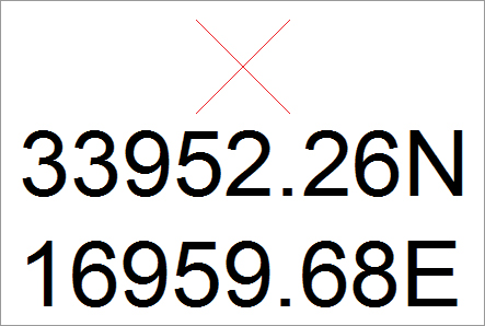
6. In Prospector, locate the point group named Group2. Right-click on Group2 and select Properties. Set the Point Label style to Northing & Easting. The labels will now resemble Figure 19-79.
Figure 19-79: Northing & Easting in the completed exercise
Sanity Saving Settings
In your Civil 3D template you will have your AutoCAD styles, linetypes, layers, Civil 3D styles, and a plethora of helpful goodies that make doing your job easier. There are a few drawing-specific CAD variables you may not have thought of that will improve your relationship with Civil 3D:
MSLTSCALE This variable stands for modelspace linetype scale. It is strongly, no, STRONGLY recommended that you have this set to 1 in your template. This setting makes line types react to your annotation scale. All your other Civil 3D objects are doing it, having your line types follow suit will help!
LAYEREVALCTL Set this to 0 to avoid the annoying pop-up that flags users when there are new layers in a drawing. Civil drafters are constantly using XRefs and inserting blocks, both of which cause the pop-up to occur.
GEOMARKERVISIBILITY This is the control for that weird thing in your drawing that appears any time a coordinate system is set up on your drawing. The geomarker looks like a block, but you can’t select it and it keeps rescaling as you zoom. Set the GEOMARKERVISIBILITY variable to 0 in your template and the geomarker won’t appear.
AUNITS This variable defines the angular units for the base CAD part of the world. Keep this set at 0 (decimal degrees) to help differentiate base AutoCAD angular entry from Civil 3D angular entry.
Line and Curve Labels
Many Civil 3D objects can have a bearing and distance label added to them. Anything from plain lines and polylines, to parcels and alignment tangent segments, can use nearly identical label types.
The examples in the following exercises will use parcels for labeling, but the tools can be applied to all other types of line labels.
Single Segment Labels
In the following exercise, you will create a new line label style that uses default components. You will remove the direction arrow and change the display precision of the direction component.
1. Open the drawing file Line and Curve Labels.dwg, which you can download from this book’s web page.
2. From the Settings tab of Toolspace, choose Parcel Label Styles Line. Right-click Line and select New.
3. On the Information tab, name the style Parcel Segment.
4. On the General tab, set the layer to C-PROP-LINE-TEXT. Leave all other General tab options at their defaults.
5. On the Layout tab, change the active component to Direction Arrow. Click the red X to delete this component.
6. Change the active component to Distance. Enter the Text Component Editor by clicking in the Text Contents area.
7. Highlight the Segment Length contents on the right by clicking on the text. All of the text should highlight as a unit.
8. On the left side of the Text Component Editor, change the Precision value to 0.01.
9. Click the arrow to update the text. Click OK to dismiss the Text Component Editor. Click OK to complete the style.
10. Add labels to the parcels by selecting the Annotate tab. Click Add Labels and set Feature to Parcel. Set the label type to Single Segment. Set Line Label Style to Parcel Segment. Click Add and select several straight segments for labeling. The completed label will resemble Figure 19-80.
Figure 19-80: Your new bearing and distance label style in action on parcel segments
Spanning Segment Labels
Looking at the labels you created in the previous exercise, you may notice that they stop at each parcel vertex. If the back property line is the same bearing, most plats show these as a single label with an overall length rather than many shorter lengths at the same bearing. To label these in Civil 3D, a separate label style is needed.
Spanning labels can be used in both line and curve parcel labels. In the following exercise, you will create line labels that span across multiple parcel segments:
1. Continue working in the drawing Line and Curve Labels.dwg.
2. From the Settings tab of Toolspace, choose Parcel Label Styles Line. Right-click Parcel Segments and select Copy.
3. On the Information tab, name the style Spanning Segment.
4. On the Layout tab, change the active Component Name to Table Tag. Change the Span Outside Segments setting to True.
5. Change to the Bearing component. Change the Span Outside Segments setting to True.
6. Change the active component to Distance. Change the Span Outside Segments setting to True. Click OK to complete the style.
7. Add labels to the parcels using the same technique you used in the previous exercise.
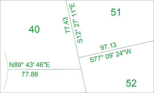
When you initially place a spanning label in the drawing, the overall length will not be reported unless the distance portion of the label is on the outside of a row of parcels. You may need to use the Flip Label command to see the spanning option take effect. Your completed label will resemble Figure 19-81.
Figure 19-81: A spanning label shown on the outside of parcel segments

Curve Labels
In base AutoCAD, creating curve labels is a chore. If you want text to align to curved objects, it is no longer usable as traditional MTEXT. Luckily, Civil 3D gives you the ability to add curved text without compromising the usability.
In the following exercise, you will create a curve label style with a delta symbol and text that curves with the parcel segment:
1. Continue working in the drawing file Line and Curve Labels.dwg.
2. From the Settings tab of Toolspace, choose Parcel Label Styles Curve. Right-click on Curve and select New.
3. On the Information tab, rename the style to Delta Length & Radius.
4. On the General tab, set Layer to C-PROP-LINE-TEXT.
5. On the Layout tab, change the active component to Distance And Radius. Enter the Text Component Editor. Highlight the Segment Length property on the right and change the precision to 0.01. Click the arrow to update the style.
6. Highlight the Segment Radius property and change the precision to 0.01. Click the arrow to update the text.
7. Delete the comma that appears as static text in the Text Component Editor. Click OK.
8. Click the Create Text Component button and in the resulting window:
- Rename the new text component to Delta.
- Change Attachment to Bottom Center.
- Change the Y offset to 0.025.
- Set Allow Curved Text to True.
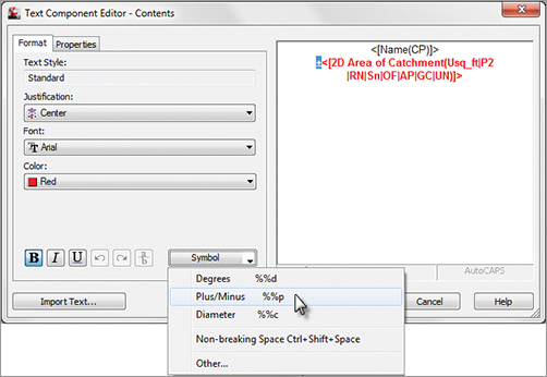
9. Enter the Text Component Editor. Remove the default label text. Switch to the Format tab. Click the Symbol button and select Other.
10. You should now see the Character Map dialog (Figure 19-82). Browse through the dialog to find the Delta symbol. When you locate it, click Select and then click Copy.
Figure 19-82: Browse for special symbols using the Windows Character Map.

11. Back in the Text Component Editor, on the right side of the dialog right-click and select Paste. Press Backspace on your keyboard if the cursor jumps to the next line of text. You should now see the delta symbol appear in the Text Component Editor.
12. Type in = as static text after the delta. Switch back to the Properties tab.
13. From the Properties drop-down, select Segment Delta Angle. Set the Format to DD° MM′ SS.SS″. Set the Precision value to 1 second. Click the arrow to place the text in the right side. Click OK to exit the Text Component Editor.
14. Click OK to complete the style.
15. Add labels to the parcels using the same technique you used in the previous exercise. Set the active curve label style to Delta Length And Radius.
Your completed label when applied to the design should resemble Figure 19-83.
Figure 19-83: Completed curve labels with delta symbol and curved text

Pipe and Structure Labels
It seems like no two municipalities label their pipes and sewer structures exactly the same way. Luckily, Civil 3D offers lots of flexibility in how you label these items.
Pipe Labels
Pipe labels have two separate label types: Plan Profile and Crossing Section. Both label types have many of the same options, but are used in different view directions.
In the following exercise, you will use a common “trick” in Civil 3D labels where a nonvisible component acts as an anchor to visible objects. In this case, you will use the flow direction arrow to force text to be placed at the ends and middle of the pipe regardless of the pipe length.
1. Open the drawing file Pipe and Structure Labels.dwg, which you can download from this book’s web page.
2. From the Settings tab of Toolspace, choose Pipe Label Styles Plan Profile. Right-click Plan Profile and select New.
3. On the Information tab, name the style Length Diameter Slope.
4. On the General tab, set the layer to C-STRM-TEXT.
5. On the Layout tab, delete the existing Pipe Text component.
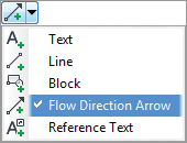
6. Click the Add New Component button and select Flow Direction Arrow; then adjust these settings:
- Set Visibility to False.
- Set Anchor Point to Top Outer Diameter.
- Set a Y offset of 0.1.
7. Click the Add New Component button and select Text. Change these settings:
- Rename the Text Component to Length.
- Set Anchor Component to Flow Direction Arrow.1.
- Set Anchor Point to Start.
- Set Attachment to Bottom Left.
- In the Text Component Editor, remove the default label text.
- From the Properties list, set 2D Length - Center to Center Current.
- Set Precision to 1 and Rounding to round up. This causes the pipe length value to round to the next highest whole foot.
- Click the arrow to place the text in the editor.
- Add a foot symbol after the text component.
- Click OK.
8. With Length as the current component, click Copy. Then change these settings:
- Rename the component to Diameter.
- Change Anchor Point to Middle.
- Change Attachment to Bottom Center.
- Enter the Text Component Editor and remove the Length text.
- From the Properties list, select Inner Pipe Diameter.
- Set the Precision to 1 and click the arrow to add the text.
- Add the inch symbol after the text component and click OK.
9. With Diameter as the current component, click Copy. Then change these settings:
- Rename the component to Slope.
- Set Anchor Point to End.
- Set Attachment to Bottom Right.
- Enter the Text Component Editor and set Pipe Slope as the current property.
- Click the arrow to update the text and click OK.
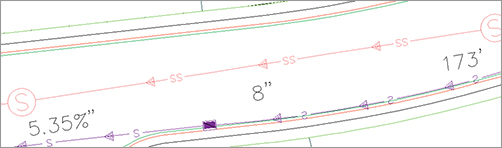
10. Click OK to complete the style. Add the label to the pipe by selecting the Annotate tab and setting the Feature option to Pipe Network and Label Type to Single Part Plan. Set the Length Diameter Slope label style to Current and click Add. Your labeled pipe will resemble Figure 19-84.
Figure 19-84: Labeled pipe using the invisible arrow trick
Structure Labels
Structure labels are nifty because they have a component no other label style has: the Text For Each component. The number of pipes entering and exiting a structure will vary depending on where the structure is in a network, and the Text For Each option accommodates that unique feature.
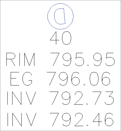
Adding Existing Ground Elevation to Structure Labels
In design situations, it’s often desirable to track not only the structure rim elevation at finished grade, but also the elevation at existing ground. This gives the designer an additional tool for optimizing the earthwork balance.
This exercise will lead you through creating a structure label that includes surface-reference text. It assumes you’re familiar with Civil 3D label composition in general:
1. Continue working in the file Pipe and Structure Labels.dwg.
2. Locate the Structure Label Styles branch on the Settings tab of Toolspace.
3. Right-click Label Styles and select New. Set the options as follows:
- On the Information tab, name the label Structure w Surface.
- On the General tab, set the layer to C-STRM-TEXT.
- On the Layout tab is a default text component called Structure Text. Set the Y offset to –0.25.
- Click in the Contents box to bring up the Text Component Editor.
- Delete the <[Description(CP)]> text string, and then use the Properties drop-down menu to add the <Name> and RIM <Insertion Rim Elevation> (two decimal places).
4. Click OK to leave the Text Component Editor.
5. In the Label Style Composer, choose Reference Text from the Add Component drop-down menu.
6. In the Select Type dialog, choose Surface.
7. Rename the component from Reference Text.1 to Existing Ground.
8. Click in the Contents box to bring up the Text Component Editor.
9. Delete the “Label Text” text string, and then use the Properties drop-down menu to add the EG <Surface Elevation> (two decimal places).
10. Click OK to dismiss the Text Component Editor.
11. In the Label Style Composer, change Anchor Component for Existing Ground to Structure Text, change Anchor Point to Bottom Center, and change Attachment to Top Center.
12. Choose the Text For Each option from the Add Component drop-down menu.
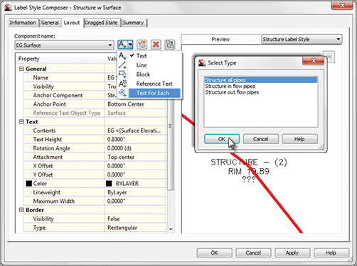
13. In the Select Type dialog, choose Structure All Pipes.
14. Click in the Contents box to bring up the Text Component Editor.
15. Delete the “Label Text” text string, and then use the Properties drop-down menu to add the INV <Connected Pipe Invert Elevation> (two decimal places).
16. Click OK to dismiss the Text Component Editor.
17. In the Label Style Composer, change Anchor Component for Text for Each.1 to Existing Ground and change Anchor Point to Bottom Center. Then, change Attachment to Top Center.
18. Click OK to dismiss the Label Style Composer.
19. Go into the drawing, and select one or more structure labels.
20. Select the Annotate tab and click Add Labels. Set the Feature option to Pipe Network and the label type to Single Part Plan. Set the structure label style to Structure w Surface and click Add.
21. Click the structure you want to label. You will immediately see a prompt at the command line that reads Select surface for label style component EG Surface :. Press ↵ to select EG from the surface listing. Your label is now complete.