
Whether we want to admit it or not, there are many other CAD programs out there and, at some point, we may need to coordinate our efforts. It can be a request for a drawing from a third party who is not using Civil 3D, or even from a different department in your organization that is using other software.
In this section, we are going to discuss and demonstrate several of such cases—because we all have to play nicely in the proverbial sandbox.
Earlier Versions of Civil 3D or Land Desktop
The majority of requests that we receive have to do with third-party clients who are using an earlier release of Civil 3D or even Land Desktop. As you may (or may not) know, the Civil 3D releases are not backward compatible—that is, if you are working in Civil 3D 2012 and want to give your design to someone who is using Civil 3D 2009, you can’t just give them your DWG file.
Even though Autodesk has a three-year cycle on drawing format, Civil 3D differs because of the new Civil 3D–specific items that are included each release.
There are a couple of ways to approach importing files and exporting your Civil 3D data, which we’ll look at next.
XML It
What Is LandXML?
LandXML is not specific to Civil 3D. It is a consortium of fellow Civil users wanting to standardize a way of sharing files in a nonproprietary format.
If you recall on the Import LandXML dialog, there was a drop-down list to select the version of LandXML. This is a result of that consortium. The latest as of this writing is the 1.2 schema. Most CAD programs have methods of importing and exporting LandXML files and this is one way to tackle that barrier.
You can read up on LandXML at www.landxml.org/.
If you want to take your drawings and make them backward compatible, then LandXML is one option. In this example, a client needs our existing and proposed surfaces on the roads:
1. Open XMLPlan.dwg, which can be found at this book’s web page.
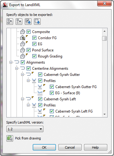
2. From the Export panel on the Output tab, select Export To LandXML. The Export To LandXML dialog shown in Figure 17-19 opens.
Figure 17-19: The Export To LandXML dialog
3. In the Export To LandXML dialog, click the Uncheck All icon. This setting does exactly as it says.
4. Click the Collapse The Tree icon, which will also do exactly as it says. These two tools are definite time-savers especially when you have the high number of items available in this dialog.
5. Expand the Surfaces section, select the Corridor FG and EG surfaces, and click OK.
6. In the Export XML dialog, navigate to the location where you wish to place the exported file. You can also rename the file. Remember the location as we will be looking for it in the next exercise. Click Save.
You have exported the files. Now let’s make sure what you exported is what you want:
1. Start a new drawing.
2. In the Import panel on the Insert tab, select LandXML.
3. In the Import LandXML dialog (Figure 17-20), navigate to the location of the previously saved XML file. Click Open.
Figure 17-20: The Import LandXML dialog

4. The Import LandXML dialog changes to reflect what it found in the file. You can select the parts that you want to be imported as well as edit any LandXML settings. Click OK to accept the defaults.
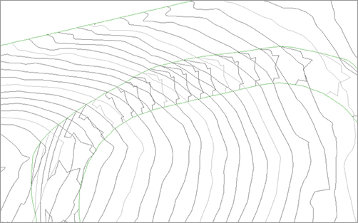
5. The file is imported into your drawing, as shown in Figure 17-21.
Figure 17-21: The imported surfaces
You will notice that it doesn’t look quite like the file you used to export. This is because of the translation process that the XML has to do. In this case, the user will get sort of what they need. It should be good enough since the areas they are concerned about are correct (in this case, the road grades for existing and proposed).
LandXML Import and Alignments
In Chapter 6, “Alignments,” you learned about the alignment constraints. New to Civil 3D 2012, when you import a LandXML file, you have the options to maintain the Free, Floating, or Fixed alignment tangency constraints.
eTransmit It
eTransmit has been around for some time. While it is not specific to Civil 3D, it is nonetheless another option for sending drawing files.
In this example, a third-party client wants our entire drawing file, but they are using AutoCAD Release 2000:
1. Open the eTransmit.dwg file.
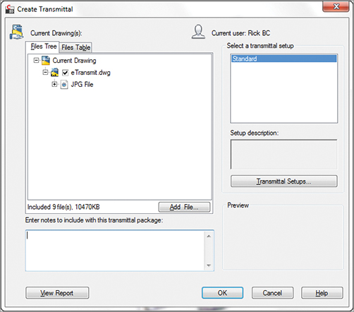
2. From the AutoCAD icon in the upper left, click Publish eTransmit. You could also type ETRANSMIT at the command prompt. The Create Transmittal dialog opens (Figure 17-22).
Figure 17-22: The Create Transmittal dialog
3. Out of the box, Civil 3D includes just a standard transmittal setup. We want to add a new setup that will allow backward compatibility for AutoCAD entities. Click the Transmittal Setups button.
4. In the Transmittal Setups dialog, click the New button. In the New Transmittal Setup dialog, type a meaningful name, such as R2000 Exploded. This would indicate that it will take the files and turn them into AutoCAD Release 2000 format and also explode any AEC entries. Click the Continue button.
5. In the Modify Transmittal Setup dialog, the most important thing to select here is the drop-down in the File format section. Make sure it is set to AutoCAD 2000 Drawing Format With Exploded AEC Objects, as shown in Figure 17-23.
Figure 17-23: The modified settings for the Modify Transmittal dialog

6. Click OK, and then close the Transmittal Setups dialog. Click OK in the Create Transmittal dialog.
7. Navigate to where you want the eTransmit file to reside. By default, eTransmit zips or packages the items into one file for ease of sending.
Note that using this method will turn any Civil 3D–specific objects into blocks. It is recommended that you explode the blocks into their native AutoCAD objects.This may be useful for the third party who is not using Civil 3D, but it’s not useful for you to receive drawings and keep all the 3D objects.
It is beyond the scope of this book to go over every detail of the eTransmit dialog. You can find more information by clicking your friendly Help icon.
Land Desktop It
The predecessor to Civil 3D, Land Desktop can be imported into Civil 3D, and with a little finagling, the imported Land Desktop objects will show up as actual Civil 3D objects.
1. Open a new drawing using the default template.
2. From the Import panel on the Insert tab, select the Land Desktop tool. The Import Data From Autodesk Land Desktop Project dialog opens.
3. By default, everything is selected. Unlike the Import XML dialog shown in an earlier exercise, there are no controls for deselecting all; you must deselect and compress the selections yourself. For this example, you are just interested in the Existing and Proposed surfaces. Make the changes as shown in Figure 17-24 and click OK.
Figure 17-24: The Import Data From Autodesk Land Desktop Project dialog

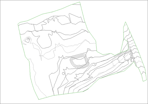
4. If everything went well, you should see no errors in the Import Data From Autodesk Land Desktop dialog. Click OK and perform a zoom extents to see your drawing, as shown in Figure 17-25.
Figure 17-25: The surfaces imported from Land Desktop
Notice that even though you started a new drawing with no coordinate set, the Land Desktop project did have a coordinate set and translates when you import into Civil 3D.
Don’t Do It! You Have Been Warned!
You may have the desire to select every object in the XML and Land Desktop import dialogs. Don’t do it! Civil 3D gets very finicky when doing these imports and you most likely will crash.
We like to think of these imports as a recipe. Mix slowly. So we recommend that you import one or two objects at a time, make the changes you want (styling, etc.), save, and then import some more. Or you can also keep the drawings separate, such as the EG in one drawing, alignments in another, and so forth.
Exporting to AutoCAD Releases
The ability to export to AutoCAD releases allows you to save your Civil 3D file as a plain AutoCAD release 2010, 2007, 2004, 2000, or release 14 format. This is also a one-way operation; it will explode any Civil 3D–specific objects. Here’s how you do it:
1. From the AutoCAD menu, choose Export AutoCAD DWG and select one of the aforementioned release formats.
2. From the Export Drawing Name dialog, select a filename and a location and then click Save.
By default, the filename will be the same one as the one you had originally opened. In addition, it will be prefixed by ACAD-.
Playing With Other Formats
In this day and age, to be competitive you must learn how to incorporate other CAD programs into Civil 3D. This section talks about these options.
Autodesk 3D Max Files
Many architectural firms use the popular Autodesk 3D Max format. Civil 3D has the capability of letting you import them.
In this example, a client who wishes to have a particular house on their newly purchased lot goes to the developer. In turn, the developer goes to the civil firm to show that house on their lot so they can visually see what it will look like before any dirt is moved. Here’s how it works:
1. Open the Import3DMax.dwg file. This drawing shows our site along with existing and proposed rough grading.
2. From the Import panel on the Insert tab, select the Import tool. The Import File dialog opens.
3. Select 3D Studio (*.3ds) from the Files Of Type drop-down list.
4. Navigate to the Pfaffle Residence.3ds file (this file is courtesy of Emmanuel Garcia) and click Open. Remember, this and all other data files can be downloaded from www.sybex.com/go/masteringcivil3d2012.
5. In the 3D Studio File Import Options dialog, click the Add All button. The dialog is shown in Figure 17-26. Click OK to dismiss the dialog.
Figure 17-26: The 3D Studio File Import Options dialog

6. Click OK on the messages that come up and perform a zoom extents. The house model has been inserted around coordinates 0,0.
7. Using the AutoCAD Block command, block the house to make it easy to insert onto the lot. Choose the option to delete the block and then erase any leftover parts. Perform another zoom extents.
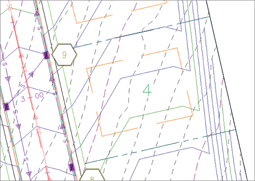
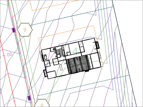
8. Zoom into your drawing so that Lot 4 is displayed as shown in Figure 17-27. The orange lines represent the maximum allowable building setback envelope by the municipality (also known as BSL).
Figure 17-27: Lot 4 shown with BSL
9. Insert the house block at the lower-left corner of the BSL. Since the house model came from an architect, you need to scale the entire block by 1/12. Next, you need to rotate it into place, as shown in Figure 17-28.
Figure 17-28: The house rotated into place
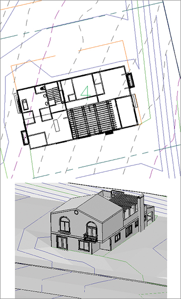
10. The house is not at the correct Z elevation. The desired building pad elevation is 800′. Click on the house block and type MOVE↵ ↵ 0,0,800↵. The finished house along with some more grading is shown in Figure 17-29.
Figure 17-29: The finished house (a) plan view (b) 3D view
Export to Civil View for 3ds Max Design
New to Civil 3d 2012 is the ability to dynamically export Civil 3D to Autodesk 3ds Max Design 2012. This tool can be found on the Export panel of the Output tab.
Importing MicroStation Files
Each release of Civil 3D provides a better method for importing and exporting MicroStation DGN files. Civil 3D 2012 is no exception. In this exercise, we have received a MicroStation DGN file that contains some roadwork:
1. Open a new drawing.
2. From the Insert tab and Import tab, select the Import tool. The Import File dialog opens.
3. At the bottom of the Import File dialog, make sure that the Files Of Type drop-down list is set to MicroStation (*.dgn).
4. Open the STPROP.dgn file (provided thanks to Matthew Anderson). Click Open. The Import DGN Settings dialog opens (Figure 17-30).
Figure 17-30: The Import DGN Settings dialog
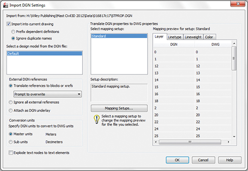
5. The Import DGN Settings dialog contains many options for handling the MicroStation file:
- At the top of the dialog, it shows you the complete path and filename that you are importing.
- When selected, the Import Into Current Drawing option allows you to insert the DGN file into your current drawing; if unchecked, it opens a new drawing and inserts it. When the box is checked, you have two choices:
- The Prefix Dependent Definitions option sets a layer prefix, as shown in Figure 17-31 (left).
Figure 17-31: The Prefix Dependent Definitions (a) and the Ignore Duplicate Names (b) result in Layer Manager
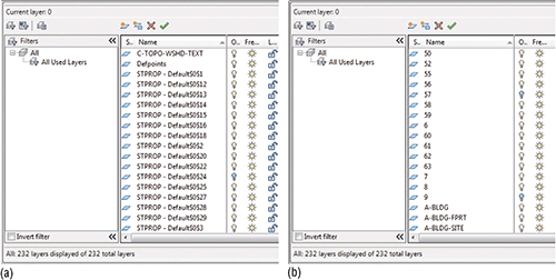
- The Ignore Duplicate Names option sets the layers as MicroStation had them, as shown in Figure 17-31 (right).
- The Prefix Dependent Definitions option sets a layer prefix, as shown in Figure 17-31 (left).
- The External DGN References section contains three radio button options:
- The Translate References To Blocks or XRefs will convert MicroStation references to blocks or XRefs; when it finds duplicates you can select a behavior via the drop-down list:
- If you choose Prompt To Overwrite, when Civil 3D finds an occurrence it will prompt you to verify that you want to overwrite a block.
- Overwrite Without Prompting is the brute-force method. It will ignore any duplicates and overwrite them regardless.
- Do Not Overwrite will skip over any duplicates, leaving them intact.
- Ignore All External References will do exactly as indicated.
- Attach DGN As Underlay will also do exactly as indicated.
- If selected, the Explode Text Nodes To Text Elements check box will take a MicroStation text node and keep the text look and feel the way it was drawn in MicroStation. This is especially important if the text was drawn in MicroStation using a path. If the option is unchecked, the text will be converted to multiline text, destroying any MicroStation formatting that may have been in place.
- The Translate DGN Properties To DWG Properties section is the meat of the process. It is similar to the Layer Translator tool. You can select a mapping setup and to the right, it shows the current mapping. By default, there is no mapping.
- Clicking the Mapping Setups button will open the DGN Mapping Setups dialog (Figure 17-32). You can create a new mapping setup, or rename, modify, or delete an existing one.
Figure 17-32: The process for DGN mapping setups

- Clicking the New button opens the New Mapping Setup dialog (Figure 17-32). Here you name your new mapping setup.
- Clicking the Mapping Setups button will open the DGN Mapping Setups dialog (Figure 17-32). You can create a new mapping setup, or rename, modify, or delete an existing one.
- Clicking Continue opens the Modify DGN Mapping Setup dialog (Figure 17-33). You can manually enter mappings to layers, linetypes, lineweights, and colors. To import properties:
Figure 17-33: The Modify DGN Mapping Setup dialog

- Clicking Add Properties From DGN File opens a dialog that lets you find a DGN file where it will import the layer properties.
- Clicking Add Properties From DWG File opens a dialog that lets you find a DWG file where it will import the layer properties.
6. Click OK and then perform a Zoom All command. Your drawing should look similar to Figure 17-34. Notice that the drawing was placed on coordinates based off the original DGN file.
Figure 17-34: The completed DGN import
DGN as Underlay
New to Civil 3D 2012 is the capability to use DGN files as underlays. On the Reference panel of the Insert tab, select Attach. In the Select Reference dialog’s Files Of Type drop-down list, select MicroStation DGN (*.dgn).
Exporting MicroStation Files
In this scenario, you will be giving our subdivision plan to a third-party client who uses MicroStation. It is a pretty straightforward process, although as you will see, there is a caveat:
1. Open the Import3DMax.dwg if it is not already open.
2. From the AutoCAD menu drop-down, select Export DGN File. The Export DGN File dialog opens.
3. Navigate to where you want the file to be placed. You can leave the default name (which is the same as the drawing), or enter your own. You can also select whether you need to save in V8 DGN or V7 DGN format.
4. Click Save.
5. The Export DGN Settings dialog opens. This is similar to the Import DGN Settings dialog we discussed earlier. Make the changes you desire and click OK.
6. You’ll see a warning message informing you that there are objects in the drawing that cannot be exported to DGN files. Your choices are to accept that fact and send the drawing without the objects or to cancel the process.
Well, that is not helpful since those objects that cannot be exported are Civil 3D–specific files—which sort of defeats the purpose. So, what do you do? You have to perform a two-part operation. As we mentioned earlier, one of the methods for exporting to plain AutoCAD and then running the DGN export will work.
So, with a little effort, you can coordinate your drawings with others and indeed, Civil 3D CAN play nicely in the sandbox with others.