
Creating Plan and Profile Sheets
Civil 3D’s Plan Production feature uses the concept of sheets to generate the pages that make up a set of plans. Simply put, sheets are layout tabs with viewports showing a given portion of your design model, based on the view frames previously created. The viewports have special properties set that define them as either Plan or Profile viewports. These viewports must be predefined in a template (DWT) file. You manage the sheets using the standard AutoCAD Sheet Set Manager feature.
The Create Sheets Wizard
After you’ve created view frames and match lines, you can proceed to the next step of creating sheets. Like view frames, sheets are created using a wizard. Let’s look at the wizard and the various page options. After you’ve walked through each page, you’ll have a chance to put what you’ve learned into practice.
You launch the Create Sheets wizard by switching to the Output tab and clicking the Create Sheets button on the Plan Production panel. A list of the wizard’s pages is shown along the left side, and an arrow indicates which page you’re currently viewing. You move among the pages using the Next and Back navigation buttons along the bottom of each page. Alternatively, you can jump directly to any page by clicking its name in the list on the left. Let’s examine the wizard’s pages and the features of each.
View Frame Group And Layouts Page
You use the first page of this wizard (Figure 16-11) to select the view frame group for which the sheets will be created. It’s also used to define how the layouts for these sheets will be generated.
Figure 16-11: Create Sheets – View Frame Group And Layouts

View Frame Group In the first section of this page, you select the view frame group either from the drop-down menu or by clicking the Select From The Drawing button to select the view frame group from the drawing. After you’ve selected the group, you use the View Frame Range option to create sheets for all frames in the group or only for specific frames of your choosing.
All Select this option when you want sheets to be created for all view frames in the view frame group.
Selection Selecting this option activates the Choose View Frames button. Click this button to select specific view frames from a list. You can select a range of view frames by using the standard Windows selection technique of clicking the first view frame in the range and then holding Shift while you select the last view frame in the range. You can also select individual view frames in nonsequential order by holding Ctrl while you make your view-frame selections. Figure 16-12 shows two of the three view frames selected in the Select View Frames dialog.
Figure 16-12: Select view frames by using standard Windows techniques.

Layout Creation In this section, you define where and how the new layouts for each sheet are created as well as the name format for these sheets, and you specify information about the alignment of the north arrow block.
There are three options for creating layout sheets: all the layout tabs are created in the current drawing (the drawing you’re in while executing the Create Sheets wizard); all the new layouts are created in a new drawing file; or the layouts are created in multiple new drawing files, limiting the maximum number of layout sheets created in each file.
Number Of Layouts Per New Drawing This option creates layouts in new drawing files and limits the maximum number of layouts per drawing file to the value you enter in the text box. For best performance, Autodesk recommends that a drawing file contain no more than 10 layouts. On the last page of this wizard, you’re given the option to select the objects for which data references will be made. These data references are then created in the new drawings.
All Layouts In One New Drawing As the name implies, this option creates all layouts for each view frame in a single new drawing. Use this option if you have fewer than 10 view frames, to ensure best performance. If you have more than 10 view frames, use the previous option. On the last page of this wizard you’re given the option to select the objects for which data references will be made. These data references are then created in the new drawings.
All Layouts In The Current Drawing When you choose this option, all layouts are created in the current drawing. You need to be aware of two scenarios when working with this option. (As explained later, you can share a view frame group via Data Shortcuts and reference it into other drawings as a data reference.)
- When creating sheets, it’s possible that your drawing references the view frame group from another drawing (rather than having the original view frame group in your current drawing). In this case, you’re given the option to select the additional objects for which data references will be made (such as alignments, profiles, pipes, and so on). These data references are then created in the current drawing. You select these objects on the last page of the wizard.
- If you’re working in a drawing in which the view frames were created (therefore, you’re in the drawing in which the view frame group exists), the last page of this wizard is disabled. This is because in order for you to create view frames (and view frame groups), the alignment (and possibly the profile) must either exist in the current drawing or be referenced as a data reference (recall the prerequisites for creating view frames, mentioned earlier).
Layout Name Use this text box to enter a name for each new layout. As with other named objects in Civil 3D, you can use the Name template to create a name format that includes information about the object being named.
Align The North Arrow Block In Layouts If the template file you’ve selected contains a north arrow block, it can be aligned so that it points north on each layout sheet. The block must exist in the template and be placed over the plan viewport. If there are multiple blocks, select the one you want to use from the drop-down menu.
Where Am I?
We strongly recommend that you set up the Name template for the layouts so that it includes the alignment name and the station range. This conforms to the way many organizations create sheets, helps automate the creation of a sheet index, and generally makes it easier to navigate a DWG file with several layout tabs.
Create Sheets Page
You use the second page of the wizard (Figure 16-13) to determine whether a new or existing sheet set (with the file extension .dst) is used and the location of the DST file. The sheet name and storage location are also defined here. Additionally, on this page you decide whether to add the sheet-set file (with the file extension.dst) and the sheet files (with the file extension.dwg) to the project vault.
Figure 16-13: Create Sheets – Sheet Set
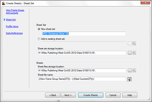
Sheet Set In this section of the page, you select whether to create a new DST file or add the sheets created by this wizard to an existing DST file.
New Sheet Set By selecting this option, you create a new sheet set. You must enter a name for the DST file and a storage location. By default, the sheet set is created in the same folder as the current drawing. You can change this by clicking the ellipsis and selecting a new location.
Add To Existing Sheet Set Selecting this option lets you select an existing sheet-set file to which the new sheets created by this wizard will be added. Click the ellipsis to browse to the existing DST file location.
Sheets You use the last section of the page to set the name and storage location for any new DWG files created by this wizard. On the previous page of the wizard, you had the choice of creating new files or creating the sheet layout in the current drawing. If you chose the latter option, the Sheets section on this page of the wizard is inactive. If you chose the former, here you enter the sheet file (DWG) name and the storage location.
What Is a Sheet?
This page can be a little confusing due to the way the word sheets is used. In some places, sheets refers to layout tabs in a given drawing (DWG) file. On this page, though, the word sheets is used in the context of Sheet Set Manager and refers to the DWG file itself.
Profile Views Page
The next page of the wizard (Figure 16-14) lists the profile view style and the band set selected in the Create View Frames wizard. You can’t change these selections. You can, however, make adjustments to other profile settings.
Figure 16-14: Create Sheets – Profile Views
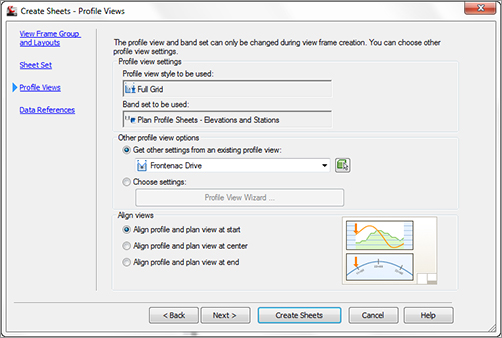
The Other Profile View Options section lets you modify certain profile view options either by running the Profile View wizard or by using an existing profile view in your drawing as an example. Regardless of what option you choose, the “other options” you can change are limited to the following:
- Split profile-view options from the Profile View Height page of the Profile View wizard
- All options on the Profile Display page
- Most of the Data Band Page settings
- Profile Hatch Options
- All settings on the Multiple Plot Options page
See Chapter 7, “Profiles and Profile Views,” for details of each of these settings.
Data References Page
The final page of the Create Sheets wizard (Figure 16-15) is used to create data references in the drawing files that contain your layout sheets.
Figure 16-15: Select Create Sheets – Data References
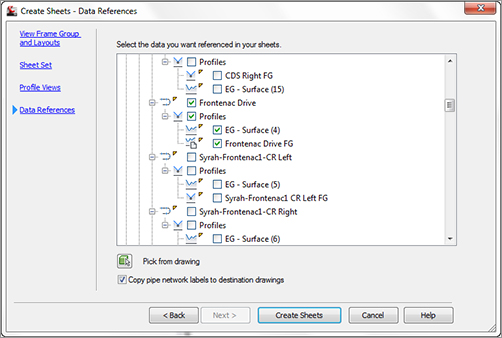
Based on the view frame group used to create the sheets and the type of sheets (plan, profile, plan and profile), certain objects are selected by default. You have the option to select additional objects for which references will be made. You can either pick them from the list or click the Pick From The Drawing button and select the objects from the drawing.
It’s common to create references to pipe networks that are to be shown in plan and or profile views. If you choose to create references for pipe-network objects, you can also copy the labels for those network objects into the sheet’s drawing file. This is convenient in that you won’t need to relabel your networks.
Managing Sheets
After you’ve completed all pages of the wizard, you create the sheets by clicking the Create Sheets button. Doing so completes the wizard and starts the creation process. If you’re creating sheets with profile views, you’re prompted to select a profile view origin. Civil 3D then displays several dialogs, indicating the process status for the various tasks, such as creating the new sheet drawings and creating the DST file.
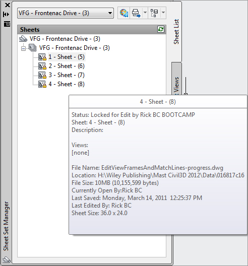
If the Sheet Set Manager isn’t currently open, it opens with the newly created DST file loaded. The sheets are listed, and the details of the drawing files for each sheet appear in the Details area (Figure 16-16).
Figure 16-16: New sheets in the Sheet Set Manager
If you double-click to open the new drawing file that contains the newly created sheets, you’ll see layout-sheet tabs created for each of the view frames. The sheets are named using the Name template as defined in the Create Sheets wizard. Figure 16-17 shows the names that result from the following template:
Figure 16-17: The template produces the Frontenac Drive tab names shown here.

<[View Frame Group Alignment Name]> <[View Frame Start Station Value]>
to <[View Frame End Station Value]>
To create the final sheets in this new drawing, Civil 3D externally references (XRefs) the drawing containing the view frames; creates data references (DRefs) for the alignments, profiles, and any additional objects you selected in the Create Sheets wizard; and, if profile sheet types were selected in the wizard, creates profile views in the final sheet drawing.
The following exercise pulls all these concepts together:
1. Open SheetsWizard.dwg, which you can download from this book’s web page. This drawing contains the view frame group, alignment, and profile for Frontenac Drive. Note that the drawing doesn’t have profile views.
2. To launch the Create Sheets wizard, click the Create Sheets button on the Plan Production panel on the Output tab of the Ribbon.
3. On the View Frame Group And Layouts page, confirm that View Frame Range is set to All and that Number Of Layouts Per New Drawing is set to 10. Click Next.
4. On the Sheet Set page, select the New Sheet Set option. For both Sheet Set File Storage Location and Sheet Files Storage Location, use the ellipsis to browse to C:Mastering Civil 3D 2012CH 16Final Sheets, and click OK. Click Next.
5. On the Profile Views page, for Other Profile View Options, select Choose Settings and then click the Profile View Wizard button. The Create Multiple Profile Views dialog opens.
6. On the left side of the Create Multiple Profile Views dialog, click Profile Display Options to jump to that page.
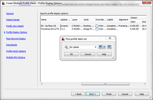
For the EG – Surface profile, scroll to the right and modify the Labels setting, changing it from Complete Label Set to _No Labels, as shown in Figure 16-18. After you select the label set, click OK; then, click Next to advance to the Data Bands page.
Figure 16-18: Change the labels for the EG – Surface profile
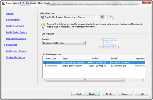
7. On the Data Bands page, change Profile2 to Frontenac Drive FG, as shown in Figure 16-19. Click Finish to return to the Create Sheets wizard. Click Next to advance to the Data References page.
Figure 16-19: Set Profile2 to Frontenac Drive FG
8. On the Data References page, confirm that Frontenac Drive and both of its profiles are selected. Click Create Sheets to complete the wizard.
9. Before creating the sheets, Civil 3D must save your current drawing. Click OK when prompted. The drawing is saved, and you’re prompted for an insertion point for the profile view. The location you pick represents the lower-left corner of the profile view grid. Select an open area in the drawing, above the left side of the site plan. Civil 3D displays a progress dialog, and then Panorama is displayed with information about the results of the sheet-creation process. Close the Panorama window.
Invisible Profile Views
Note that the profile views are created in the current drawing only if you selected the option to create all layouts in the current drawing. Because you didn’t do that in this exercise, the profile views aren’t created in the current drawing. Rather, they’re created in the sheet drawing files in model space in a location relative to the point you selected in this step.
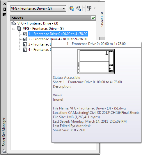
10. After the sheet-creation process is complete, the Sheet Set Manager window opens (Figure 16-20). Click sheet 1, named Frontenac Drive 0 + 00.00 to 4 + 78.00. Notice that the name conforms to the Name template and includes the alignment name and the station range for the sheet. Review the details listed for the sheet. In particular, note the filename and storage location.
Figure 16-20: The Sheet Set Manager once the sheet-creation process is complete
11. Double-click this sheet to open the new sheets drawing and display the layout tab for Frontenac Drive 0 + 00.00 to 4 + 78.00. Review the multiple tabs created in this drawing file. The template used also takes advantage of AutoCAD fields, some of which don’t have values assigned.