
Using View Frames and Match Lines
When you create sheets using the Plan Production tool, Civil 3D first automatically helps you divide your alignment into sections that will fit on your plotted sheet and display at the desired scale. To do this, Civil 3D creates a series of rectangular frames placed end to end (or slightly overlapping) along the length of alignment, like those in Figure 16-1. These rectangles are referred to as view frames and are automatically sized and positioned to meet your plan sheet requirements. This collection of view frames is referred to as a view frame group. Where the view frames abut one another, Civil 3D creates match lines that establish continuity from frame to frame by referring to the previous or next sheet in the completed plan set. View frames and match lines are created in model space, using the prerequisite elements described in the previous section.
Figure 16-1: View frames and match lines
The Create View Frames Wizard
The first step in the process of creating plan sets is to generate view frames. Civil 3D provides an intuitive wizard that walks you through each step of the view frame creation process. Let’s look at the wizard and the various page options. After you’ve seen each page, you’ll have a chance to put what you’ve learned into practice.
You launch the Create View Frames wizard (Figure 16-2) by selecting the Create View Frames button on the Plan Production panel found on the Output tab of the Ribbon. The wizard consists of several pages. A list of these pages is shown along the left side, and an arrow indicates which page you’re currently viewing. You move among the pages using the Next and Back navigation buttons along the bottom of each page. Alternatively, you can jump directly to any page by clicking its name in the list on the left. The following sections walk through the pages of the wizard and explain their features.
Figure 16-2: The Create View Frames wizard
Alignment Page
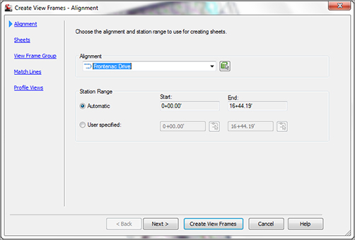
You use the first page to select the alignment and station range along which the view frames will be created.
Alignment In the first section of this page, you select the alignment along which you want to create view frames. You can either select it from the drop-down menu or click the Select From The Drawing button to select the alignment from the drawing.
Station Range In the Station Range section, you define the station range over which the frames will be created. Selecting Automatic creates frames from the alignment Start to the alignment End. Selecting User Specified lets you define a custom range, by either keying in Start and End station values in the appropriate box or by clicking the button to the right of the station value fields and graphically selecting the station from the drawing.
An example of selecting specific stations is if you have a subdivision that will be constructed in phases. You have designed an entire roadway but only need to create specific sheets for a specific phase.
Sheets Page
You use the second page of the wizard (Figure 16-3) to establish the sheet type and the orientation of the view frames along the alignment. A plan production sheet is a layout tab in a drawing file. To create the sheets, Civil 3D references a predefined drawing template (with the file extension .dwt). As mentioned earlier, the template must contain layout tabs, and in each tab the viewport’s extended data properties must be set to either Plan or Profile. Later in this chapter, you’ll learn about editing and modifying templates for use in plan production.
Figure 16-3: Create View Frames – Sheets

Sheet Settings In Civil 3D, the Plan Production feature provides options for creating three types of sheets:
Plan And Profile This option generates a sheet with two viewports; one viewport shows a plan view and the other shows a profile view of the section of the selected alignment segment.
Plan Only As the name implies, this option creates a sheet with a single viewport showing only the plan view of the selected alignment segment.
Profile Only Similar to Plan Only, this option creates a sheet with a single viewport, showing only the profile view of the selected alignment segment.
Graphics
Did you notice the nifty graphic to the right of the sheet-type options in Figure 16-3? This image changes depending on the type of sheet you’ve selected. It provides a schematic representation of the sheet layout to further assist you in selecting the appropriate sheet type. You’ll see this type of graphic image throughout the Create View Frame wizard and in other wizards used for plan production in Civil 3D.
After choosing the sheet type, you must define the template file and the layout tab within the selected template that Civil 3D will use to generate your sheets. Several predefined templates ship with Civil 3D and are part of the default installation.
Clicking the ellipsis button displays the Select Layout As Sheet Template dialog. This dialog provides the option to select the DWT file and the layout tab within the template. Clicking the ellipsis button in that dialog lets you browse to the desired template location. Typically the default template location is:
C:Users<username>AppDataLocalAutodeskC3D2012
enuTemplatePlan Production
If you are on a network environment, your templates might be found in a common folder on the network.
After you select the template you want to use, a list of the layouts contained in the DWT file appears in the Select Layout As Sheet Template dialog (Figure 16-4). Here you can choose the appropriate layout.
Figure 16-4: Use the Select Layout As Sheet Template dialog to choose which layout you would like to apply to your newly created sheets.

View Frame Placement Your view frames can be placed in one of two ways: either along the axis or rotated north. Use the bottom section of the Sheets page of the wizard to establish the placement.
Along Alignment This option aligns the long axes of the view frames parallel to the alignment. Refer to the graphic to the right for a visual representation of this option.
Rotate To North As the name implies, this option aligns the view frames so they’re rotated to the north directions (straight up), regardless of the changing rotation of the alignment centerline. North is defined by the orientation of the drawing. Again, refer to the graphic.
If you want the north arrow to rotate according to the view twist of the viewport, the block that is being used for the north arrow must be included in the template and must be located over the plan viewport.
Set The First View Frame Before The Start Of The Alignment By Regardless of the view frame alignment you choose, you have the option to place the first view frame some distance before the start of the alignment. This option is useful if you want to show a portion of the site, such as an existing offsite road, in the plan view. When this option is selected, the text box becomes active, letting you enter the desired distance.
View Frame Group Page
You use the third page of the Create View Frames wizard (Figure 16-5) to define creation parameters for your view frames and the view frame group to which they’ll belong. The page is divided into two sections: one for the view frame group and the other for the view frames themselves.
Figure 16-5: Create View Frames – View Frame Group
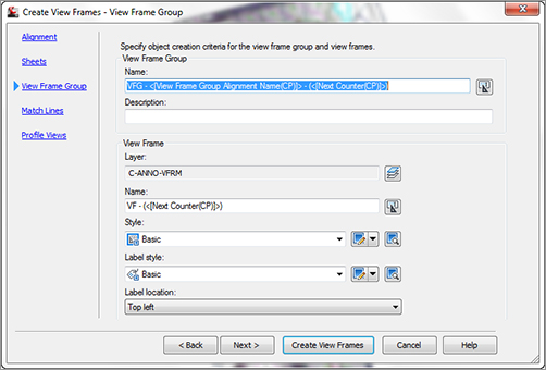
View Frame Group Use these options to set the name and an optional description for the view frame group. The name can consist of manually entered text, text automatically generated based on the Name Template settings (click the Edit View Frame Name button to open the Name Template dialog to adjust the name template), or a combination of both. In this example, the feature settings are such that the name will include manually defined prefix text (VFG-) followed by automatically generated text, which inserts the alignment name and a sequential counter number. For this example, this will result in a view frame group name of VFG – Frontenac CL - 1.
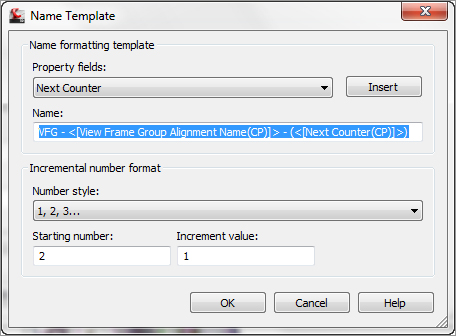
The Name Template dialog isn’t unique to the Plan Production feature of Civil 3D. However, the property fields available vary depending on the features to be named. If you need to reset the incremental number counter, use the options in the lower area of the Name Template dialog (Figure 16-6).
Figure 16-6: The Name Template dialog. Use the options in the Incremental Number Format section to adjust automatic numbering.
View Frame These options are used to set various parameters for the view frames, including the layer for the frames, view frame names, view frame object and label styles, and the label location. Each view frame can have a unique name, but the other parameters are the same for all view frames. Setting the view frame layer to no-plot will ensure your drawing does not end up plotting with unwanted rectangles.
Layer This option defines the layer on which the view frames are created. This layer is defined in the drawing settings, but you can override it by clicking the Layer button and selecting a different layer.
Name The Name setting is nearly identical in function to that for the view frame group name discussed earlier. In this example, the default name results in VF-1, VF-2, and so on.
Style Like nearly all objects in Civil 3D, view frames have styles associated with them. The view frame style is simple, with only one component: the view frame border. You use the drop-down menu to select a predefined style.
Label Style Also like most other Civil 3D objects, view frames have label styles associated with them. And like other label styles, the view frame labels are created using the Label Style Composer and can contain a variety of components. The label style used in this example includes the frame name and station range placed at the top of the frame.
Label Location The last option on this page lets you set the label location. The default feature setting places the label at the Top Left of the view frame. Other options include Top Center, Top Right, Bottom Left, Bottom Right, and so on.
All view frame labels are placed at the top of the frame. However, the term top is relative to the frame’s orientation. For alignments that run left to right across the page, the top of the frame points toward the top of the screen. For alignments that run right to left, the top of the frame points toward the bottom of the screen. You can make the view frame label display along the frame edge closest to the top of the screen by using a large Y-offset value when defining your view frame label style.
Match Lines Page
You use the next page of the Create View Frames wizard (Figure 16-7) to establish settings for match lines. Match lines are used to maintain continuity from one sheet to the next. They’re typically placed at or near the edge of a sheet, with instructions to “see sheet XX” for continuation. You have the option whether to automatically insert match lines. Match lines are used only for plan views, so if you’re creating Plan And Profile or Profile Only sheets, the option is automatically selected and can’t be deselected.
Figure 16-7: Create View Frames – Match Lines
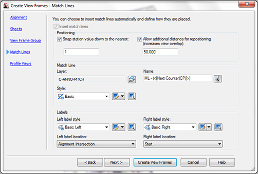
Positioning The Positioning options are used to define the initial location of the match lines and provide the ability to later move or reposition the match lines.
Snap Station Value Down To The Nearest By selecting this option, you override the drawing station settings and define a rounding value specific to match-line placement. In this example, a value of 1 is entered, resulting in the match lines being placed at the nearest whole station. This feature always rounds down (snap station down as opposed to snap station up).
Allow Additional Distance For Repositioning Selecting this option activates the text box, allowing you to enter a distance by which the views on adjacent sheets will overlap and the maximum distance that you can move a match line from its original position.
Match Line The options for the match line are similar to those for view frames described on the previous page of the wizard. You can define the layer, the name format, and the match-line style.
Labels These options are also similar to those for view frames. Different label styles are used to annotate match lines located at the left and right side of a frame. This lets you define match-line label styles that reference either the previous or next station adjacent to the current frame. You can also set the location of each label independently using the Left and Right Label Location drop-down menus. You have options for placing the labels at the start, end, or middle, or at the point where the match line intersects the alignment.
Profile Views Page
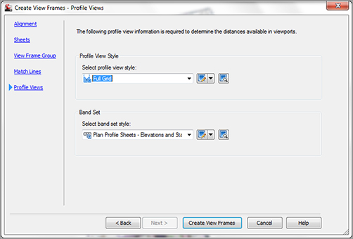
The final page of the Create View Frames wizard is the Profile Views page (Figure 16-8). This page is optional and will be disabled and skipped if you chose to create Plan Only sheets on the second page of the wizard. The Plan Production feature needs to know what profile view and band set styles you intend to use for the profile views. This allows the correct positioning to be applied. Use the drop-down menus to select both the profile view style and the band set style.
Figure 16-8: Create View Frames – Profile Views
Civil 3D has difficulty determining the proper extents of profile views. If you find that your profile view isn’t positioned correctly in the viewport (for example, the annotation along the sides or bottom is clipped), you may need to create buffer areas in the profile view band set style by modifying the text box width. The _Autodesk Civil 3D NCS.dwt (both Imperial and Metric) file contains styles with these buffers created.
This last page of the wizard has no Next button. To complete the wizard, click the Create View Frames button.
Creating View Frames
Now that you understand the wizard pages and available options, you’ll try them out in this exercise:
1. Open ViewFrameWizard.dwg, which you can download from this book’s web page at www.sybex.com/go/masteringcivil3d2012. This drawing contains several alignments and profiles as well as styles for view frames, view frame groups, and match lines.
2. To launch the Create View Frames wizard, click the Create View Frames button on the Plan Production panel on the Output tab of the Ribbon.
3. On the Alignment page, select Frontenac Drive from the Alignment drop-down menu. For Station Range, verify that Automatic is selected, and click Next to advance to the next page.
4. On the Sheets page, select the Plan And Profile option.
5. Click the ellipsis button to display the Select Layout As Sheet Template dialog. Then, click the next ellipsis and browse to the Plan Production subfolder in the default template file location. Typically, this is:
C:Users<username>AppDataLocalAutodeskC3D2012
enuTemplatePlan Production
6. Select the template named Civil 3D (Imperial) Plan and Profile.dwt, and click Open.
7. A list of the layouts in the DWT file appears in the Select Layout As Sheet Template dialog. Select the layout named ARCH D Plan and Profile 20 Scale, and click OK.
8. In the View Frame Placement section, select the Along Alignment option. Then, select Set The First View Frame Before The Start Of The Alignment By. Note that the default value for this particular drawing is 30′. Click Next to advance to the next page.
9. On the View Frame Group page, confirm that all settings are as follows (these are the same settings shown previously in Figure 16-5), and then click Next to advance to the next page:
| Setting | Value |
| View Frame Group Name | VFG - <[View Frame Group Alignment Name(CP)]> - (<[Next Counter(CP)]>) |
| View Frame Name | VF - (<[Next Counter(CP)]>) |
| Style | Basic |
| Label Style | Basic |
| Label Location | Top Left |
10. On the Match Lines page, review the default settings and click Next to advance to the next page.
11. On the last page of the wizard, confirm that the settings are as follows (these are the same settings shown previously in Figure 16-8), and then click Create View Frames:
| Setting | Value |
| Select Profile View Style | Full Grid |
| Select Band Set Style | Plan Profile Sheets - Elevations And Stations |
The view frames and match lines are created and are displayed as a collection in Prospector, as shown in Figure 16-9.
Figure 16-9: Finished view frames in the drawing and in Prospector
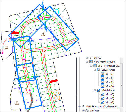
The numbering for your view frames, view frame groups, and match lines may not identically match that shown in the images. This is due to the incremental counting Civil 3D performs in the background. Each time you create one of these objects, the counter increments. You can reset the counter by modifying the name template.
Editing View Frames and Match Lines
After you’ve created view frames and match lines, you may need to edit them. Edits to some view-frame and match-line properties can be made via the Prospector tab in the Toolspace palette. For both view frames and match lines, you can only change the object’s name and/or style via the Information tab in the Properties dialog. All other information displayed on the other tabs is read-only.
You make changes to geometry and location graphically using special grip edits (Figure 16-10). Like many other Civil 3D objects with special editing grips (such as profiles and Pipe Network objects), view frames and match lines have editing grips you use to modify the objects’ location, rotation, and geometry. Let’s look at each separately.
Figure 16-10: View frame and match line grips
View frames can be graphically edited in three ways. You can move them, slide them along the alignment, and rotate them as follows:
To Move a View Frame The first grip is the standard square grip that is used for most typical edits, including moving the object.
To Slide a View Frame Select the view frame to be edited, and then select the diamond-shaped grip at the center of the frame. This grip lets you move the view frame in either direction along the alignment while maintaining the orientation (Along Alignment or Rotated North) you originally established for the view frame when it was created.
To Rotate a View Frame Select the frame, and then select the circular handle grip. This grip works like the one on pipe-network structures. Using this grip, you can rotate the frame about its center.
Don’t Forget Your AutoCAD Functions!
While you’re getting wrapped up in learning all about Civil 3D and its great design tools, it can be easy to forget you’re sitting on an incredibly powerful CAD application.
AutoCAD features add functionality beyond what you can do with Civil 3D commands alone. First, make sure the DYN (Dynamic Input) option is turned on. This gives you additional functionality when you’re moving a view frame. With DYN active, you can key in an exact station value to precisely locate the frame where you want it. Similar to view frame edits, with DYN active, you can key in an exact rotation angle. Note that this rotation angle is relative to your drawing settings (for example, 0 degrees is to the left, 90 degrees is straight up, and so on). Also, selecting multiple objects and then selecting their grips while holding Shift makes each grip “hot” (usually a red color). This allows you to grip-edit a bunch of objects at once, like sliding a group of view frames along the alignment.
Whether you’re learning Civil 3D yourself or training a group, it’s a good idea to spend some time looking at the new AutoCAD features with every new release. You never know when you’ll discover a nugget that cuts hours off your workday!
You can edit a match line’s location and length using special grips. As with view frames, you can slide them along the alignment and rotate them. They can also be lengthened or shortened. Unlike view frames, they can’t be moved to an arbitrary location.
To Slide a Match Line Select the match line to be edited, and then select the diamond-shaped grip at the center of the match line. This grip lets you move the match line in either direction along the alignment while maintaining the orientation (Along Alignment or Rotated North) that you originally established for the view frame. Note that match line can only be moved in either direction a distance equal to or less than that entered on the Match Line page of the wizard at the time the view frames were created. For example, if you entered a value of 50′ for the Allow Additional Distance For Repositioning option, your view frames are overlapped 50′ to each side of the match line, and you can slide the match line only 50′ in either direction from its original location.
To Rotate a Match Line Select the match line, and then select the circular handle grip. This grip works like the one on a view frame.
To Change a Match Line’s Length When you select a match line, a triangular grip is displayed at each end. You can use these grips to increase or decrease the length of each half of the match line. For example, moving the grip on the top end of the match line changes the length of only the top half of the match line; the other half of the match line remains unchanged. See the sidebar “Don’t Forget Your AutoCAD Functions!” for tips on using AutoCAD features.
The following exercise lets you put what you’ve learned into practice. Make sure Dynamic Input is active:
1. Continue working in the drawing from the previous exercise or open EditViewFramesAndMatchLines.dwg from this book’s web page. This drawing contains view frames and match lines. You’ll change the location and rotation of a view frame and change the location and length of a match line.
2. Select the lower middle view frame, which consists of stations 9+56 to 14+34, and select its diamond-shaped sliding grip. Slide this grip up so the overlap with the lower view frame isn’t so large. Either graphically slide it to station 11+00 or enter 1100 in the Dynamic Input text box. Notice that the view frame label is updated with the revised stations.
3. Press Esc to clear your selection. Select the circular rotation grip on the lower view frame that consists of stations 14+34 to 16+44. Rotate the view frame slightly to better encompass the road. In the Dynamic Input text box, enter 8. Then, press Esc to clear the grips from the view frame.
4. Now you’ll adjust the match line’s location and length. Select the Match Line, which is presently at Station 14+34, and then select its diamond sliding grip. Either graphically slide it to station 13+25 or enter 1325 in the Dynamic Input text box. Notice that the match line label is updated with the revised station.
5. Next, you’ll lengthen the right side of the match line so it extends the width of the view frame. Select the triangular lengthen grip at the lower end of the Match Line, and either graphically lengthen it to 125′ or enter 125 in the Dynamic Input text box. Press Esc to exit the command.