
Just like with parcels and labels, labeling pipes can turn into a mess with all the labels set on the plan, such as pipes and structures (see Figure 13-74). In this section, you will explore table creation for pipes and structures.
Figure 13-74: Pipes and structures labeled on a plan

In the following exercise, you will create a pipe network table for the sanitary sewer structures:
1. Open the CreatingPipeTables.dwg file which you can download from this book’s web page.
2. Click on the Sanitary Sewer Manhole 1.
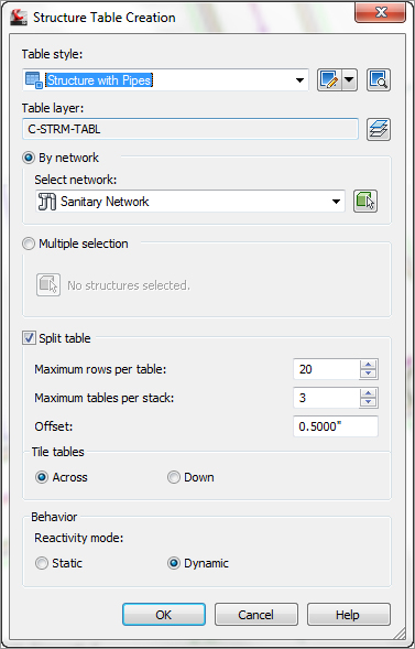
3. From the Labels & Tables panel, select Add Tables Add Structure. The Structure Table Creation dialog opens (Figure 13-75).
Figure 13-75: The Structure Table Creation dialog
4. Click OK to accept the default settings. Place the table to the right of your plan. The table should look similar to Figure 13-76.
Figure 13-76: The finished structure table

The table creation for pipes is similar to the structure table creation process:
1. Click on a Sanitary Sewer pipe.
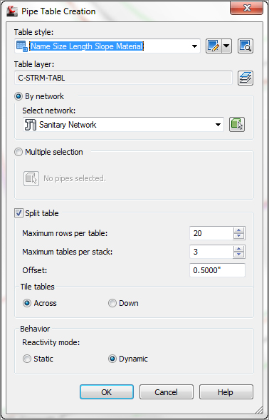
2. From the Labels & Tables panel, select Add Tables Add Pipe. The Pipe Table Creation dialog opens (Figure 13-77).
Figure 13-77: The Pipe Table Creation dialog
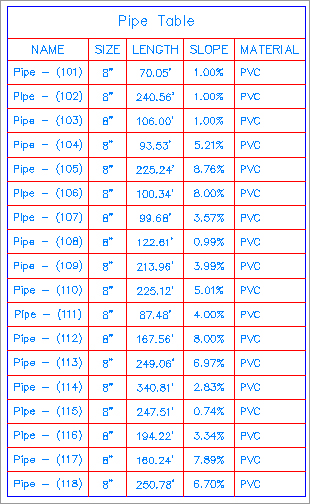
3. Click OK to accept the default settings. Place the table to the right of the structure table. The pipe table should look similar to Figure 13-78.
Figure 13-78: The finished pipe table
Exploring the Table Creation Dialog
Since the structure and pipe table creation dialogs are similar, we will cover both of them in this section.
- The Table Style option allows you to select a table look or style. You can select the available styles from the arrow to the right of the table style name. You can also create new, copy, edit, or pick a table style. For more on table styles, see Chapter 19.
- The Table Layer option will set the overall layer for the table.
- With the By Network radio button selected, you can select the network to create a table from the drop-down list, or by using the pick icon, which will allow you to pick the network on the drawing.
- With the Multiple Selection radio button selected and by using the pick icon, you can select structures or pipes (depending on which table type is selected) from the drawing. You can pick pipes or structures regardless of the network.
- The Split table check box will allow you to split the table if it gets too large. You can specify the maximum number of rows per table and maximum number of tables per stack. Additionally, you can set the offset distance between the stacked tables.
- You can choose whether you want the split tables tiled across or down.
- The last option to choose defines the behavior you want for the table: Static or Dynamic. A static table will not update if any changes are made to the pipe network, such as swapping a part. Dynamic will update the table to those changes.
Changes to a Pipe Network and Pipe Tables
Let’s see how a predefined table reacts with network changes by following this exercise:
1. Open the PipeTableStaticDynamic.dwg file. This drawing contains two identical structure tables except one is static and one is dynamic.
2. Click on the sanitary sewer pipe that is between structure 1 and structure 2.
3. From the Modify panel, select Pipe Properties.
4. In the Pipe Properties dialog, select the Part Properties tab and change Start Invert Elevation from 818.476′ (249.47 m) to 800.000′ (243.84 m). This change is extreme and won’t make sense on the actual design, but is meant to show the dynamic relationship between the pipe network and the structure table.
5. Click OK and compare the table that has been set to static versus the table set to dynamic.
The Table Panel Tools
When you click on a table, the Table panel opens and has several tools available. We’ll look at each in this section.
The General Tools Panel
The tools here are the same as mentioned earlier when we discussed the pipe network tools.
The Modify Panel
The Modify Panel contains the following tools:
Table Properties Tool Opens the Table Properties dialog. You can set the table style and choose whether to split the table with all the options mentioned earlier. In addition, you can force realignment of stacks and force content updating.
Edit Table Style Tool Opens the Table Style dialog. For more on editing table styles, see Chapter 19.
Static Mode Tool Turns a dynamic table into a static table.
Update Content Tool Forces an update on a table.
Realign Stacks Tool Readjusts the table columns back to the default setting.
Add Items Tool Adds additional pipe data to the table added after the table was created.
Remove Items Tool Removes pipe or structure objects from a table.
Replace Items Tool Allows you to swap pipe or structures in the table.