
Creating a Single-Section View
There are occasions when all section views are not needed. In these situations, a single-section view can be created. In this exercise, you create a single-section view of station 5 + 50 from the sample lines created in the previous exercise:
1. Continue with sections1.dwg, or you can open the sections3.dwg file.
2. Change to the Home tab and choose Section Views Create Section View from the Profile & Section Views panel. The Create Section View Wizard appears.
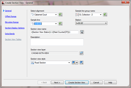
3. Make sure the settings in the Create Section View Wizard match the settings shown in the following figures. The first screen of the wizard is the General page, shown in Figure 12-10. It allows you to select the alignment, sample line group name, desired sample line or station, and the section view style. You can navigate from one page to another by either clicking Next at the bottom of the screen or clicking the links on the left side of the screen.
Figure 12-10: The General page of the Create Section View Wizard
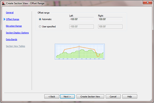
The second page is where you specify the offset range, as shown in Figure 12-11. You can make the section views the same width by entering a user-specified offset or specify that the width of the section view be controlled by the width of the sample line.
Figure 12-11: The Offset Range page of the Create Section View Wizard
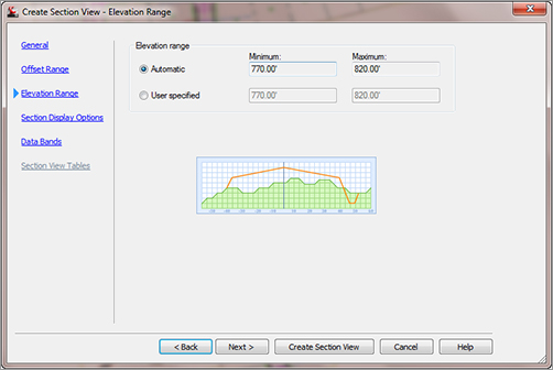
The third page, shown in Figure 12-12, is where you choose the elevation range. You can specify that the height of the section view be set automatically based on the depth of cut or fill, or make it a consistent height by clicking the User Specified radio button and entering an elevation range.
Figure 12-12: The Elevation Range page of the Create Section View Wizard
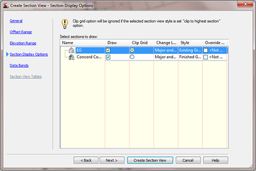
The fourth page contains the section display options, as shown in Figure 12-13. On this page, you can pick which sections to draw in the view, indicate if and how you want the grid clipped in the section view, and specify section view labels and section styles.
Figure 12-13: The Section Display Options page of the Create Section View Wizard
The fifth page, shown in Figure 12-14, lets you specify the data band options. Here, you can select band sets to add to the section view, pick the location of the band, and choose the surfaces to be referenced in the bands.
Figure 12-14: The Data Bands page of the Create Section View Wizard

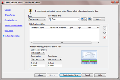
The sixth and last page, shown in Figure 12-15, is where you set up the section view tables. Note that this screen will be available only if you have already computed materials for the sample line group. On this page, you can select the type of table and the table style, and select the position of the table relative to the section view. Notice the graphic on the right side of the window that illustrates the current settings.
Figure 12-15: The Section View Tables page of the Create Section View Wizard
4. Select Create Section View.
5. Pick any point in the drawing area to place your section view.
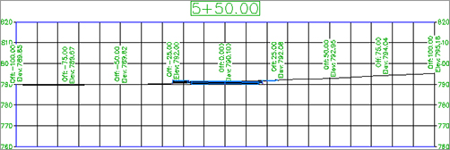
6. Examine your section view. The display should match Figure 12-16.
Figure 12-16: The finished section view
7. Close the drawing without saving.
Section View Object Projection
Civil 3D has the ability to project AutoCAD points, blocks, 3D solids, 3D polylines, AutoCAD Civil 3D COGO points, feature lines, and survey figures into section and profile views. Each of the objects listed can be projected to a section view and labeled appropriately. See Chapter 7, “Profiles and Profile Views,” to learn more. You access the command by changing to the Home tab’s Profile And Section Views panel and selecting Section Views Project Objects To Section.