
Photorealistic Visualization
When compared to analytic visualization, photorealistic visualization is more concerned with the emotive, experiential qualities of your space and content. Materials are carefully selected for accuracy and real-world simulation. But quite often, real-world isn't enough. Put another way, if analytic visualization is about what something means, photorealistic visualization is about how something feels or is experienced.
In many cases you'll find yourself tweaking materials and lighting in order to “theatrically” increase the nature of the space. Embellishing your project with nonproject entourage is probably essential, and we'll cover important techniques to keep that content from cluttering up the views that are necessary for documentation. In addition, lighting is key, which means you'll have to contend with considerably longer rendering times.
Visual Styles
In this section, we'll describe the various visual styles that are available in the View Control Bar with regard to rendering. Even though these settings create photorealistic renderings, their settings affect the outcome of renderings. Figure 12.31 shows the View Control Bar of an orthographic view. Figure 12.32 shows the View Control Bar of a perspective view. The major difference is that orthographic views are set to a scale.
FIGURE 12.31 2D and orthographic View Control bar
![]()
FIGURE 12.32 Perspective View Control bar
![]()
Note that 2D project views can't be rendered. But you can orient an orthographic view to a 2D orientation and render.
LEVEL OF DETAIL
The first option controls the level of detail in the view (Figure 12.33).

What is visible by default in a view is initially determined by the scale of the view, as shown by selecting Manage ![]() Additional Settings
Additional Settings ![]() Detail Level. Figure 12.34 shows the default settings.
Detail Level. Figure 12.34 shows the default settings.
FIGURE 12.34 View scale-to-detail level
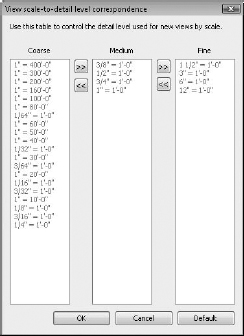
But this level of detail setting can be overridden after the view is created. This fact is important for two reasons. First, changing the scale after the view is created will not automatically reset the level of detail, and second, rendering a view with a more granular detail level will (generally speaking) take more time. Even though the results will not be visible to the naked eye, the calculations required to render what you won't be able to discern (because the objects are so small) will still be computed.
So, it's very important that you render at the appropriate level of detail.
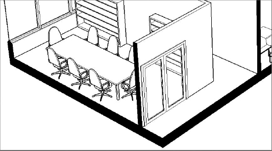
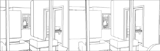
To illustrate this, look at the two perspectives in Figure 12.35. Although these two views look identical, one will rotate, refresh, and render faster than the other. This is because they're also set to different levels of detail.
FIGURE 12.35 Nonidentical views

The reason is not discernable at this scale because the differences are barely a pixel in size. The view on the left is set to a Coarse level of detail. But the view on the right is set to a Fine level of detail. Although this different detail level doesn't have much of an effect on the content in either view, there is a critical difference.
The Executive Chair family has been modified so that the casters at the base of the chair only display at a Fine level of detail. The results are shown in Figure 12.36.
FIGURE 12.36 Detail level of chair
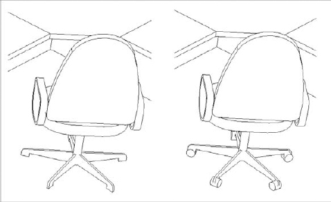
This difference may not have a large effect on a small project, yet it can have a significant effect on your project when you render (not to mention the additional time it will take when you export and print). So, be sure that before you render a view, the level of detail is appropriately set. If you're far away from the building or your view is quite broad, a Coarse detail level is quite sufficient. But if you're zoomed in on a particular detail or part of the building (or just a single office or room), a Fine detail level might be more appropriate.
VISUAL STYLES AND GRAPHIC DISPLAY
The visual style of your view can be one of six settings (Figure 12.37).
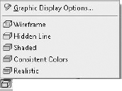
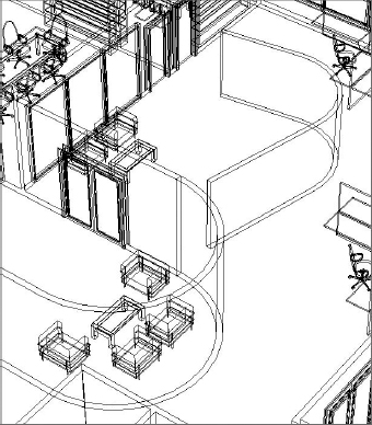
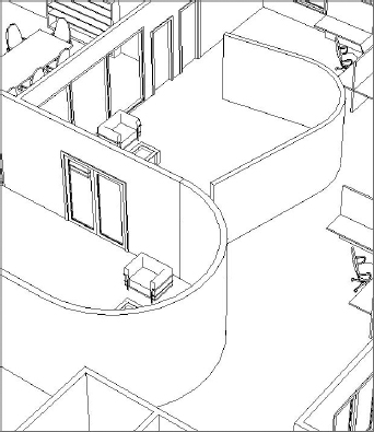
The Wireframe view (Figure 12.38) maintains only the edges of objects. Faces are hidden.
Hidden Line keeps both the edges and faces visible (Figure 12.39).
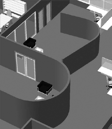
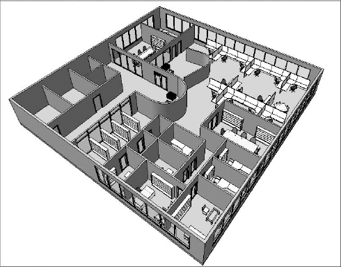
The Shaded view shows faces in their shaded value without accentuated edges (Figure 12.40). Note the change in color depending on an object's orientation. This effect is particularly pronounced on curved surfaces.

Shaded With Edges is simply the Shaded view but with edges shown (Figure 12.41). Again, the color of the object is the shaded value but relative to the orientation of the object to the viewer.
FIGURE 12.41 Shaded With Edges view

Consistent Colors view removes the color variation based on an object's orientation to the viewer. Colors are strict interpolations of the shaded value (Figure 12.42) and, therefore, have a flatter yet more consistent appearance.
FIGURE 12.42 Consistent Colors view

The Realistic setting provides real-time overlays of geometry with the material that will be used during a photorealistic rendering, as shown in Figure 12.43.
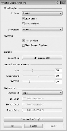
Graphic Display Options allow you to control all of your views' graphic options, including Ghost Surfaces (Figure 12.44).
FIGURE 12.44 Graphic Display Options

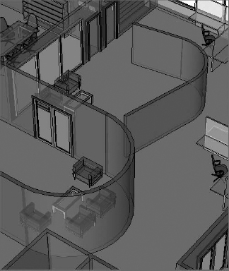
When the Ghost Surfaces option is selected, all previously opaque surfaces become 30 percent transparent (70 percent opaque), while maintaining their shaded and material settings (Figure 12.45). When this option is selected, it's not possible to select the Cast Shadows option.
SHADOWS
We've already discussed the sun settings, so in this section we'll move ahead to the Shadows On/Off settings (Figure 12.46). You click the button to toggle shadows on or off.
![]()
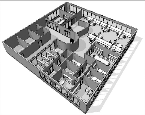
The ability to turn shadows on in real time is a terrific feature that helps you add an improved sense of depth to your view (Figure 12.47).
Keep a couple of things in mind when turning on shadows. First, screen refreshing takes a bit longer when shadows are turned on. So you'll probably want to keep shadows off in your working views as you zoom in, zoom out, and rotate.
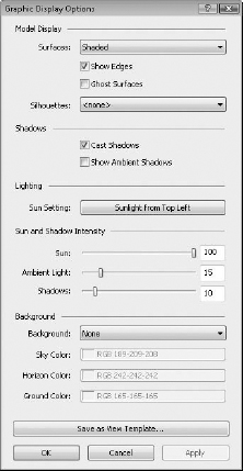
Second, the default settings could use adjusting. To do this, open the Graphic Display Options dialog box, as shown in Figure 12.48.
FIGURE 12.47 Default Shadows On

FIGURE 12.48 Graphic Display Options dialog box
Unless you're doing a solar study, the default sun setting should probably be set to Sunlight From Top Right or Sunlight From Top Left (Figure 12.49).
FIGURE 12.49 Choosing Sunlight From Top Left

The more that you increase the Sun Intensity setting (Figure 12.50), the more washed out your view's appearance.
FIGURE 12.50 Increased Sun Intensity setting

Turning the shadows off can have an appealing effect that softens the shaded materials in your view considerably (Figure 12.51).
If you're going to turn shadows on, experiment by decreasing the default Cast Shadows value (Figure 12.52). Doing so will keep the shadows on in your view but not overwhelm it with dramatic changes in lit and nonlit areas (Figure 12.53).
FIGURE 12.52 Decreased Cast Shadows value
The Silhouette Style option allows you to override the edges of objects when that edge is defined by space (Figure 12.54). In Figure 12.55, the image on the left illustrates the view without silhouettes, and the image on the right shows the view with Wide Lines enabled.
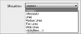
FIGURE 12.55 No silhouettes vs. Wide Lines silhouettes

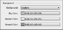
Selecting the Background option allows you to simulate a horizon without rendering. Figure 12.56 shows the default settings.
FIGURE 12.56 Background settings
Ambient Light and Shadows
The ambient light and shadows, combined with other graphic options such as edge enhancements and real-time materials, allow you to create emotive, real-time views of your project that do not require renderings.
To activate ambient light and shadows, open the Graphic Display Options dialog box and select both Ambient Light and Show Ambient Shadows, as shown in Figure 12.57. Deselect the Show Edges option.
FIGURE 12.57 Ambient light and shadows

The results are subtle but noticeable, particularly around the intersections of like objects. Shaded elements are embellished by highlights in the center of objects and deeper shading at the edges, as shown in Figure 12.58. The result is almost a water-colored effect that considerably softens the shaded view. The effect can be accentuated when combined with the option to enhance the silhouette of edges for even more real-time effects (Figure 12.59).
FIGURE 12.58 Activating ambient light and shadows
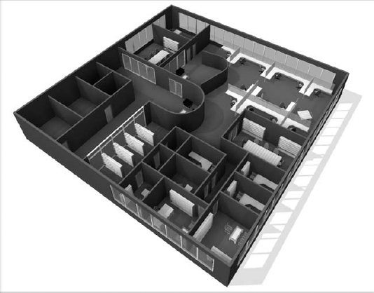
FIGURE 12.59 Ambient lighting with edges

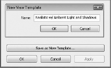
If you'd like to preserve the graphic display settings for other views, select Save As View Template directly from the Graphic Display Options dialog box (Figure 12.60). Then you'll be prompted to name your new view template.
FIGURE 12.60 Saving the view template
Once you click OK, you'll be taken directly to the View Templates dialog box, where you can further refine the view's settings. Click OK when you're satisfied with the settings (Figure 12.61).
FIGURE 12.61 View Templates dialog box

Section Box
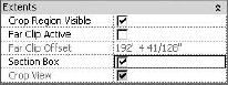
Before we get into the rendering process, let's discuss the section box. By selecting the Section Box option, as shown in Figure 12.62, you create a rectilinear matrix around your project that may be pushed and pulled to isolate a portion of your project.
FIGURE 12.62 Activating the section box
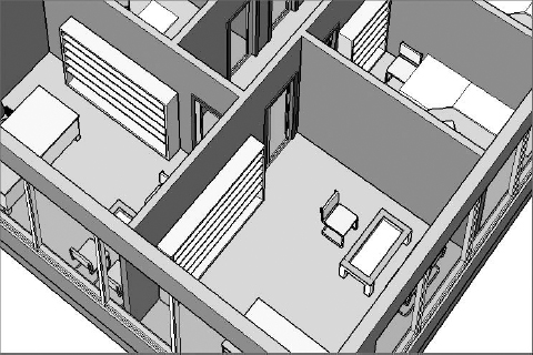
In Figure 12.63, the section box has been pulled to isolate a portion of the project. This technique is helpful for isolating a smaller portion of a larger project. But a word of warning: Be careful turning the section box off and on. The extents of the section box will reset and you'll have to pull them back into place. Very frustrating!
FIGURE 12.63 Pulling the section box to isolate a portion of the project
If you open the type properties of the view, you'll notice that there's a setting to determine the color of the poche (Figure 12.64).

The poche can be seen in all display types (Wireframe through Realistic), but it is only displayed in a view that is set to the Coarse level of detail. We recommend that you set the default color to black.
Here's why. As shown in Figure 12.65, the regions between host elements (like the walls and floors) are shown as discrete geometries. Yet it's often more desirable to show the poche as solid across these boundaries.
FIGURE 12.65 Regions between host elements are shown as discrete geometries.

You can use the Join Geometry option to clean up the lines between elements. But this approach is time-consuming and often leads to other problems in your file when a lot of things get “joined” just to create graphic impression.
Ideally, you'd like to have the option to “graphically” join the regions between these elements so that they appear monolithic without using the Join Geometry tool. That way, you could select a nice color that would stand out from the rest of the model and communicate the cut plane. Maybe in the next release!
In the meantime, one simple way to clean this up graphically is to select a poche color that is the same as the color of the lines between elements: black. Again, it's not the most desirable result, but it's fast, doesn't require manual joining of geometry, and reads well (Figure 12.66).
FIGURE 12.66 Solid poche black
Rendering Settings
![]() You can access the Rendering dialog box by clicking the teapot icon on the View tab or at the base of the view in the Visual Styles bar. Figure 12.67 shows the Rendering dialog box.
You can access the Rendering dialog box by clicking the teapot icon on the View tab or at the base of the view in the Visual Styles bar. Figure 12.67 shows the Rendering dialog box.
FIGURE 12.67 Rendering dialog box

An important setting in this dialog box is the resolution. It's easy to spend far too much time creating a rendered view, because rendering times increase exponentially when the resolution doubles. Think of it this way. If you're rendering a view at 150 dots per inch (dpi) and then you render the same view at 300 dpi, the image is now four times larger, not twice as large (1 × 1 = 1 and 2 × 2 = 4). If you were to render the view at 600 dpi, it would be 16 times larger (4 × 4 = 16), and you could reasonably expect the 150 dpi image that rendered in a few minutes to take considerably longer at 600 dpi.
How large you need to render something depends on what you're going to use it for: screen or print. Don't expect a rendering the size of a 3″ × 5″ postcard to work for a 3′ × 5′ banner.
So, what resolution is big enough? Well, it's probably better to render things a bit larger, which will give you some flexibility if you need to increase the size of your image later.
Revit provides five present quality settings (Figure 12.68).

Figure 12.69 and Figure 12.70 illustrate the range between the Draft and the Best settings.


The Output Settings (Figure 12.71) help you determine the level of resolution that your image can be saved at when rendered. The screen resolution is simply the resolution of the view on your monitor.

You should be much more interested in the printer settings because of the likelihood that you'll need to print your views. Again, the resolution is important, because you're printing for something that will be viewed at some distance (arm's length or a few feet away) with the naked eye. Rendering beyond what can reasonably be seen will add a lot of time to your renderings. While the default printer resolutions are shown in Figure 12.72, you can input other values by typing them in the dialog box.

Estimating your image resolution is easy. If the image is going to be viewed on a screen, 150 dpi is likely sufficient and even gives you some flexibility if the image has to be slightly larger. If you need to print the image, 300 dpi will work the vast majority of the time. Now take the longest dimension of your image (height or width) and multiply the dimension by the needed resolution. That's it!
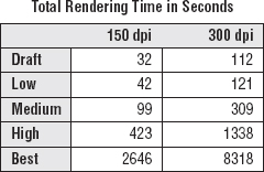
Here's a test. Figure 12.73 was rendered at each default setting of the screen resolution. The image size was only 3″ × 2″—very small to be practical, but it was sufficient to chart render times rendering at 150 dpi and 300 dpi.
We kept the image small so the renderings could compute faster, and we left the lighting scheme to Exterior: Sun only and set the background color to solid white. As you can see in Figure 12.74, the time to complete each setting does not increase linearly. This fact is important to keep in mind as you change your quality settings and resolution, especially between High and Best, because there is a greater than six times increase in rendering time! Make sure the increase in time is worth the effort.
FIGURE 12.74 Quality render times
Creating Your View
Creating and modifying your camera controls is almost as important as what you're creating. If you're not careful, you can easily under-impress the viewer by selecting the wrong view and aspect ratio of camera and controls.
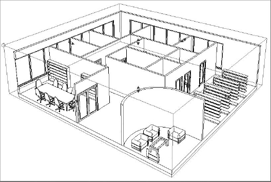
Perspective views communicate far more depth than orthographic views (Figure 12.75). Unless the view needs to be at dimensioned scales, we prefer to use perspective views of the project.
FIGURE 12.75 Orthographic vs. perspective view

Locking Your View
Once you've created your view, you might want to consider locking your view so it can't be accidentally rotated (Figure 12.76). Once your view is locked, you'll also be able to tag elements in your view.
FIGURE 12.76 Lock view settings
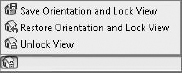
There are three options available from the Lock 3D View option. Save Orientation And Lock View keeps the current orientation and prohibits anyone from rotating the view. Once this option is selected, the Keynote command on the Annotations tab becomes available.
Selecting Restore Orientation And Lock View allows an unlocked view to be returned to its previously saved orientation and re-locked. Any tags and keynotes that were previously placed in the view are restored.
Selecting Unlock View unlocks the view and allows you to orbit and navigate the view. But keep in mind that when you unlock the view, any placed tags and keynotes disappear—and if you save the view from the unlocked and modified state, any tags and keynotes previously placed in the view are deleted.
Still Image Camera
When you create your camera view, the first point to select is your eye elevation, and the second point is the target elevation. Keep in mind that when you rotate your view, the rotation is centered on the target elevation (Figure 12.77).
FIGURE 12.77 Placing the camera

Also, realize that there is effectively a boundary box, which defines the extents of your camera view. You can see this by going to another view, like a plan, and then selecting the camera from your Project Browser, as shown in Figure 12.78.
Once you can see your camera, you can select and move it around your project. Doing so allows you to move your camera closer and farther. You can also select the clipping planes of your camera and edit the front and back planes of your camera's view.
The aspect ratio of your camera is also important. For example, a television ratio of 4:3 seems far less expansive and dramatic than a 16:9 widescreen ratio. Figure 12.79 illustrates this; the image on the left is 4:3 and the image on the right is 16:9. The result is that the view on the left seems too tight and constrained, whereas the view on the right is far more natural.
FIGURE 12.78 Selecting Show Camera

To change the aspect ratio, select the view boundary and then select the Size Crop option on the Modify Camera tab. In the resulting dialog box, you can change the aspect proportionally or nonproportionally (Figure 12.80). Keep in mind this setting doesn't zoom your camera forward and backward; it simply changes the relative height and width of the view.
FIGURE 12.80 Crop Region Size dialog box

To dolly your camera, simply activate the Navigational Wheel (Figure 12.81). You'll be able to zoom, pan, and orbit as well as control other view features.
FIGURE 12.81 Navigational Wheel

Animation Path
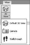
Creating an animation path is much like creating a series of cameras. To create a camera path, select the Walkthrough option from the View tab (Figure 12.82).
FIGURE 12.82 Creating the walkthrough
From your plan view, start placing a series of cameras. Note that each time you pick a location, these cameras will become the key frames in your animation. When you have placed the last camera, press the Esc key, and your finished path will appear (Figure 12.83).
FIGURE 12.83 Finished camera path

Right-clicking the path will allow you to go to the series of views that you just created (Figure 12.84).
FIGURE 12.84 Going to the camera view

We'll be the first to admit that the walkthrough tools are not very intuitive. Figure 12.85 shows the first view in the path that we've just created along with the Walkthrough view properties.
FIGURE 12.85 Walkthrough properties

Let's modify the aspect ratio to 16:9. Select the view boundary and select Size Crop. By default, the view is 6″ × 4 ½″. An 8″ × 4 ½″ ratio is proportionally 16:9 (Figure 12.86). The view is now wider and less constrained.
FIGURE 12.86 Setting the aspect ratio

We're going to export a Hidden Line view for testing (especially before rendering), but we want to give the walkthrough more depth. So change the silhouette edge style to wide lines (Figure 12.87).
FIGURE 12.87 Setting the graphic display options

It's not desirable to simply walk with the camera facing the same direction that you're walking. So you're going to modify the camera. But this will require that you open a couple of views, as shown in Figure 12.88. This way, you'll be able to see the results of your work in one view in other views.
FIGURE 12.88 Tiled camera and views

A couple of important points should be noted. First, you're showing the plan and the camera view at the same time. This allows you to see both the graphic and analytic camera, which is important for modifying views. As you can see, when you select the boundary of the view on the right, the camera path highlights in the view on the left.
Since the view is selected, you have the option of editing the crop size just like any other camera. But you also have the option of editing the walkthrough, as shown in Figure 12.89.
FIGURE 12.89 Edit Walkthrough option

Click the Edit Walkthrough option, and you'll be given the context toolbar, as shown in Figure 12.90.

After you open the Key Frame Editor, the camera path now shows important controls (Figure 12.91).
FIGURE 12.91 Camera path and controls

The red dots along the path represent key frame locations (when you placed your camera, remember?), and the red dot directly in front of the camera will allow you to control the rotational direction. By default, all the cameras face ahead relative to their location on the path. But you can edit the default so that the camera can follow one direction but face another direction.
Since the default path is 300 frames in length, it would take a long time to go to each frame and edit what you see. It's better to jump ahead from key frame to key frame, editing fewer locations. When you do this, Revit will interpolate the frames between the key frames for you. As you jump ahead key frame to key frame, try to experiment rotating the camera to the left and right as well as glancing up and down. This can be done from the plan view on the left or from the camera view on the right.
Once you've edited your key frames, you can export the animation from the Export menu, as shown in Figure 12.92.
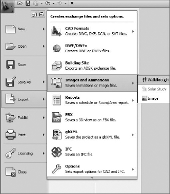
You'll be given options to export an AVI with all the rendering options that you're given for still images (Figure 12.93).
FIGURE 12.93 Graphic format controls
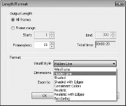
A 15 frame-per-second (fps) frame rate is minimal to keep the animation smooth. But if you increased the frame rate, the animation length would shorten and it would seem like you were running (rather than walking) through the scene. What can you do? Simply add more frames to your animation.
At the bottom of the camera properties, open the Walkthrough Frames dialog box (Figure 12.94). By increasing the total frames, you can also adjust the relative fps in order to maintain the desired speed.
FIGURE 12.94 Default frame count

So, for example, if you wanted to increase the fps to 30 but maintain the same travel speed, you would also increase the Total Frames setting to 600 (see Figure 12.95). Simple!
FIGURE 12.95 Increasing the frame count
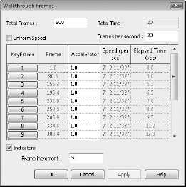
Finally, where a lot of people struggle is with the speed of their animation. Unless you're breaking up your animation into separate paths (which will be combined later into a single sequence), it's necessary to be able to speed up or slow down your camera's movement. In Revit, you can uncheck the Uniform Speed option in order to speed up or slow down the camera during a single animation study.
Although there's no exact rule for this, you can imagine the results. Think about how a plane seems to speed up relative to the ground as it approaches to land. In fact, it's slowing down. Yet your relative distance to the ground influences the perception of how fast you're moving. So even though you're slowing down, as you get closer to the ground, it seems like you're moving faster. And when you're at 30,000 feet, it seemed like you were barely moving at all. Just imagine how the astronauts feel in space. Although it might seem like they're barely moving at all and the earth slowly spins below, in fact they're orbiting at over 17,000 miles per hour. Don't hit any space junk!
The same visual effect plays a part in your renderings. The farther you are from something, the faster your camera can move as you fly by and still seem smooth and fluid. But you will need to slow down considerably if you're walking through the building, where a comfortable pace is 6–8 feet a second.
We've exported the animation from this portion of the chapter. If you want to investigate the file or animation, you can download the c12_Visualization.rvt file or the c12_Visualization_Animation.avi from the Chapter 12 folder.