
Exporting 3D Model Data
You can also export your Revit model as a 3D model in several formats for use in other modeling software. A frequent destination for such data is Autodesk 3ds Max for its enhanced rendering and daylighting analysis capabilities. This workflow is supported by the FBX export format, which includes not only model geometry but materials, cameras, and lights as well. More generic exports in DWG, DGN, DXF, or SAT formats can provide numerous opportunities for you to become more creative with the presentation of your designs.
Studies in Google SketchUp
Earlier in this chapter we discussed using Google SketchUp for conceptual building massing studies. These studies were imported directly into the Revit environment for further development of a true building information model. Revit model data can also be exported via 3D DWG to Google SketchUp, where visualization studies can be conducted on an entire project or even a simple wall section. In the following exercise, we will create a wall section study from Revit to Google SketchUp using files you can download from the book's web page.
- Open the file c08-Sketchup-Wall-Study.rvt.
- Activate the default 3D view and enable the Section Box option in the Properties Palette for the view.
- Set the detail level of the view to Medium or Fine.

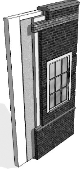
- Activate the section box in the properties of the 3D view and shape handles will appear on each face. Grab the shape handle of one side of the section box parallel to the vertical edge of the wall sample and drag toward the wall until the section box intersects the wall, as shown in Figure 8.40. You should see the layers of the wall structure exposed.
FIGURE 8.40 Using the section box to expose the layers of the wall
- With the section box still selected, right-click and choose Hide In View
 Elements, as shown in Figure 8.41. This will prevent the section box from being exported.
FIGURE 8.41 Hide the section box to prevent it from exporting.

- Click the Application menu and select Export CAD Formats DWG Files.
- In the Export CAD Formats dialog box, switch to the DWG Properties tab and set the Solids option to Export As Polymesh.
- Click Next and save the DWG file to a location on your computer or network.
- Launch Google SketchUp, and choose File Import.
- Switch the Files Of Type option to AutoCAD Files, navigate to the file saved in step 8, and click Open.
- Switch to the Select tool, select the entire DWG import, right-click, and choose Explode. This will allow you to directly edit the elements in the SketchUp environment. Note that other components within the exploded model may need to be exploded again.

Once the DWG model is loaded in Google SketchUp, you can use the Paint Bucket tool to apply materials to individual components, use the Push/Pull tool to hide or expose layers of the wall construction, and use the line tools to customize the profile of the revealed layers, as shown in Figure 8.42.
FIGURE 8.42 Completed wall study in Google SketchUp
IFC Interoperability
According to Wikipedia, “Industry Foundation Classes (IFC) is a data model based on a neutral and open specification that is not controlled by a single software vendor or group of vendors. It is an object-oriented file format with a data model developed by the buildingSMART Alliance (International Alliance for Interoperability, IAI) to facilitate interoperability in the building industry.” The IFC model specification is registered by the International Standards Organization (ISO) as ISO/PAS 16739 and is currently in the process of becoming the official International Standard ISO/IS 16739. Because of its focus on ease of interoperability between BIM software platforms, some government agencies are requiring IFC format deliverables for publicly funded building projects.
The use of IFC format in a Revit workflow can be useful if you understand its limitations. Some scenarios where IFC exchange may apply and facilitate data exchange include, but are not limited to, the following:
- Linking AutoCAD MEP into Revit
- Using Solibri Model Checker
- Coordination between Revit and Nemetschek Allplan, VectorWorks, or ArchiCAD
You can export the Revit model quite effectively to the IFC 2x2, 2x3, or BCA ePlan Check formats by clicking the Application menu and selecting the flyout menu. The resulting IFC file (Figure 8.43) can be viewed in a number of programs that can be downloaded at no cost from any of the following websites:
- DDS CAD Viewer from Data Design System (www.dds-cad.net)
- Nemetschek IFC Viewer (www.nemetschek.com/ifc)
- IFC Engine Viewer (www.ifcbrowser.com)
FIGURE 8.43 Revit model exported to IFC format

Importing IFC data into Revit is similar to the process for importing 3D CAD geometry; however, the data generated is intended to be more intelligent and editable. Although this method has great potential, the accuracy of Revit's IFC import is highly dependent on the software used to generate the IFC output. We recommend the use of one of the free IFC viewers listed previously to inspect IFC data prior to importing into a Revit project. (Note that only some tools, such as DDS CAD Viewer, have the ability to measure objects in an IFC format file.)
VIEWING THE CONTENTS OF AN IFC FORMAT FILE
Did you know that an IFC file can be viewed in a text editor such as Notepad? Download a sample file from the book's companion web page and check it out! Right-click an IFC file, select Open With, and choose Notepad.
Once you've reviewed the contents of the IFC file, you can open it in Revit and integrate it into your coordination process as follows:
- Click the Application menu, and select Open IFC.
- Navigate to the c08-Structure.ifc file and click Open.
- Save the file as a Revit project file (*.rvt).
- Start a new Revit project using the default template. You will link the saved RVT file into a blank project to simulate the process for a host project model.
- On the Insert tab, select Link Revit from the Link panel.
- Navigate to the file saved in step 3, and click Open.
If an updated IFC file is received, repeat steps 1–3, and overwrite the RVT file created in step 3. When the host project file is reopened, the linked RVT file containing the imported IFC content will be updated.
![]() Real World Scenario: 3D EXPORTS BY LEVEL
Real World Scenario: 3D EXPORTS BY LEVEL
Effective coordination between Revit Architecture and AutoCAD MEP frequently relies on the exchange of 3D DWG files of limited scope with respect to the overall project. MEP engineers using AutoCAD MEP will usually manage their BIM with one model file per level. Even though the entire architectural model can be exported to a single DWG model, they may not be able to reference such a large model efficiently. The good news? Your Revit project can be set up to achieve this by creating 3D views with section boxes for each level.
Begin by creating a series of floor plans designed for exporting (discussed earlier in this chapter). In the View Range settings for these plans, set the Top value to Level Above, Offset: 0 and the Bottom value to Associated Level, Offset: 0. Create a 3D view for each level required in the project and rename the views according to your standards. In each duplicated 3D view, right-click the ViewCube and select Orient To View ![]() Floor Plans and choose the corresponding floor plan with the adjusted view range. This series of 3D views can be saved in an export list and batch exported to 3D DWG when needed for collaboration, as shown here:
Floor Plans and choose the corresponding floor plan with the adjusted view range. This series of 3D views can be saved in an export list and batch exported to 3D DWG when needed for collaboration, as shown here:
