
Exporting 2D CAD Data
When collaborating with others who require 2D CAD, planning a strategic workflow will allow you to share your Revit data more efficiently and consistently. We highly recommend that you determine and document the scope of data to be shared, the schedule by which it will be shared, and the software platforms to be used on a project. These aspects should be compiled in a BIM execution plan as explained in Chapter 7, “Working with Consultants.”
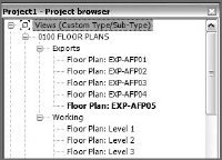
To facilitate the setup and ultimate export of plan data, you can create copies of floor plans and ceiling plans with a standardized naming convention in your Revit project. These should be easy to recognize yet help in building the export list. In Figure 8.25, a series of duplicated plans have been created and named with the EXP- prefix. The rest of the view name conforms to the naming convention specified by the US National CAD Standard (www.nationalcadstandard.org).
FIGURE 8.25 View organization for plans to be exported
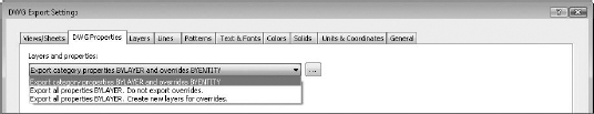
When it is time to export floor plans or ceiling plans, make sure you are using the most appropriate settings according to the conventions your team has established in the BIM execution plan. You can find these settings in the DWG Export Setup dialog box, as shown in Figure 8.26. Each setting is organized under its own tab, and these settings can be saved and used across multiple projects.
FIGURE 8.26 DWG properties for exporting

DWG Settings for Export
The following are the default DWG settings for exporting for each tab in the DWG Export Settings dialog box:
DWG Properties “Export category properties BYLAYER and overrides BYENTITY” will maintain the most visual fidelity to what you see in Revit. If you anticipate that the recipient of your CAD file will use scripts or macros to enforce their own graphic standards, select the “Export all properties BYLAYER” option and don't export overrides (Figure 8.27).
FIGURE 8.27 DWG properties for exporting
Layers The Layers tab lets you designate export layer options as well as load layers from other standards (Figure 8.28).
FIGURE 8.28 Layer properties for exporting

Selecting the Layer Modifiers button opens a further dialog box that lets you customize select layer properties (Figure 8.29).
FIGURE 8.29 Modifying layer properties for exporting

Lines The Lines tab lets you carefully control how lines are generated from Revit (Figure 8.30), and the default setting lets Revit automatically generate them to match what is shown in Revit.
FIGURE 8.30 Lines properties for exporting

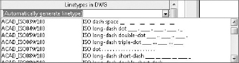
But if you want to deviate from the automatically generated linetype, you can make a selection from the Linetypes In DWG drop-down menu (Figure 8.31).
FIGURE 8.31 Custom line properties for exporting
Patterns The Patterns tab allows you to control how patterns are exported from Revit (Figure 8.32). By default, Revit automatically generates them to match what is shown in your Revit file.
If you need to generate patterns that differ from what is shown in your Revit files, select from the Hatch Pattern In DWG drop-down menu (Figure 8.33).
Text & Fonts The Text & Fonts tab allows you to control mapping of fonts and text from Revit to AutoCAD. The default selection generates fonts to match what is shown within Revit (Figure 8.34).
FIGURE 8.32 Pattern properties for exporting

FIGURE 8.33 Custom pattern properties for exporting

FIGURE 8.34 Text and font properties for exporting

To export a text or font that is different from what is shown in Revit, select from the Text Fonts In DWG drop-down menu (Figure 8.35).
FIGURE 8.35 Custom text and font properties for exporting

Colors The Colors tab allows you to export colors based either on the Color ID specified on the Layers tab or as an RGB value from the view in Revit (Figure 8.36).
FIGURE 8.36 Color properties for exporting

Solids The Solids tab has two options for exporting, either Polymesh or ACIS solids (Figure 8.37). You can select either option only if you have selected a 3D view for export. Otherwise the options are grayed out and you can't select either.
FIGURE 8.37 Solid properties for exporting

Units And Coordinates The Units And Coordinates tab lets you select the units for export (imperial or metric) as shown in Figure 8.38. You can also select the coordinate system, either Revit's own internal coordinate system or a user-defined system.
FIGURE 8.38 Unit and coordinate properties for exporting

General The General tab gives you control over the export of room and area lines (Figure 8.39). Select this option if you want the lines to export as a single polyline that you can query from your AutoCAD file.
FIGURE 8.39 Unit and coordinate properties for exporting
